


17
115895B System Installation Manual
C H A P T E R 6
I
NSTALLING
B
ATTERIES AND
DC
W
IRING
WARNING
Only qualified service personnel (such as a licensed electrician) should perform the
battery and DC wiring installation. There is a risk of electrical shock.
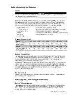
This section explains how to install system batteries, fuses, and cables. For all models, you
must install the batteries in the system cabinet. An electrician who is familiar with battery
installations and applicable building and electrical codes should install the batteries.
WARNING
The batteries that will need to be installed in this system could cause you harm or severely
damage the electronics if proper precautions are not followed. Batteries connected in series
parallel configuration could produce lethal voltages with unlimited current. All batteries
should be inspected for damage prior to installation. Never install a battery that is leaking
electrolyte. Battery terminals should be cleaned with a wire brush to remove any oxidation.
All tools should be insulated. Rubber gloves and safety glasses are recommended.
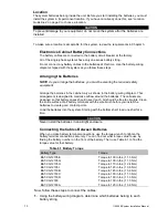
IN THIS
SYSTEM BATTERY NEGATIVE IS TIED TO GROUND INSIDE THE INVERTER.
This
means that the cabinet and shelves are at ground potential as soon as negative connections
are made to the batteries. It is strongly recommended to make all negative connections to
the batteries the last step to prevent any chance of shorting battery positive to ground. With
the DC fuse(s) removed, make connections to battery positive first, working your way towards
battery negative. Leave individual strings of batteries open at the last battery negative until
all batteries are installed. Then connec
t each string’s negative.
Safety Instructions
IMPORTANT SAFETY INSTRUCTIONS
SAVE THESE INSTRUCTIONS
This section contains important instructions that a qualified service person should
follow during installation and maintenance of the system and batteries. ONLY a
qualified service person should work with the batteries.
CAUTION
Full voltage and current are always present at the battery terminals. The batteries used
in this system can produce dangerous voltages, extremely high currents, and a risk of
electric shock. They may cause severe injury if the terminals are shorted together or to
ground (earth). You must be extremely careful to avoid electric shock and burns
caused by contacting battery terminals or shorting terminals during battery installation.
Do not touch un-insulated battery terminals.
Summary of Contents for Illuminator Supernova Series
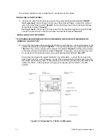
Page 16: ...15 115895B System Installation Manual Figure 5 2 AC Connections for 6 25 k W 7 5 kW systems ...
Page 17: ...16 115895B System Installation Manual Figure 5 3 AC Connections for 10 kW 16 7 kW systems ...
Page 30: ...115895B System Installation Manual PART II OPTIONS MANUALS Section continues on next page ...
Page 95: ...94 115895B System Installation Manual SERIAL TO ETHERNET ADAPTER OPTION SECTION ...
Page 96: ...95 115895B System Installation Manual SERIAL TO ETHERNET ADAPTER OPTION SECTION ...
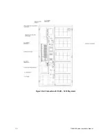
Page 114: ...113 115895B System Installation Manual DRAWINGS SECTION ...
Page 115: ...114 115895B System Installation Manual DRAWINGS SECTION ...
Page 116: ...115 115895B System Installation Manual DRAWINGS SECTION ...
Page 117: ...116 115895B System Installation Manual DRAWINGS SECTION ...
Page 118: ...117 115895B System Installation Manual DRAWINGS SECTION ...
Page 119: ...118 115895B System Installation Manual DRAWINGS SECTION ...
Page 120: ...119 115895B System Installation Manual DRAWINGS SECTION ...
Page 121: ...120 115895B System Installation Manual DRAWINGS SECTION ...
Page 122: ...121 115895B System Installation Manual DRAWINGS SECTION ...
Page 123: ...122 115895B System Installation Manual DRAWINGS SECTION ...
Page 124: ...123 115895B System Installation Manual DRAWINGS SECTION ...
Page 125: ...124 115895B System Installation Manual DRAWINGS SECTION ...
Page 126: ...125 115895B System Installation Manual DRAWINGS SECTION ...
Page 127: ...126 115895B System Installation Manual DRAWINGS SECTION ...
Page 128: ...127 115895B System Installation Manual DRAWINGS SECTION ...
Page 129: ...128 115895B System Installation Manual DRAWINGS SECTION ...
Page 130: ...129 115895B System Installation Manual DRAWINGS SECTION ...
Page 131: ...130 115895B System Installation Manual Notes ...


