76
115895B System Installation Manual
MODBUS TCP & SNMP COMMUNICATION OPTION SECTION
SECTION 5
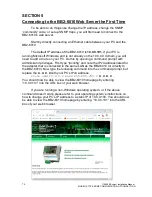
Connecting to the BB2-6010 Web Server the First Time
To be able to do things like change the IP address, change the SNMP
‘community’ code, or set up SNMP traps, you will first need to connect to the
BB2-6010
’s web server.
Start by directly connecting an Ethernet cable between your PC and the
BB2-6010.
The default IP address of the BB2-6010 is
10.0.0.101
. If your PC is
running Microsoft Windows, and is not already on the 10.0.0.0 domain, you will
need to add a route on your PC. Do this by opening a command prompt with
administrator privileges. First typ
e “ipconfig” and note the IPv4 address listed for
the adapter that is connected to the same LAN as the BB2-6010 (or directly to
the BB2-6010). Now type the following command into the command prompt, but
replace the
X.X.X.X
with your PC
’s IPv4 address.
route add 10.0.0.0 mask 255.255.255.0
X.X.X.X
You should now be able to view the BB2-6010 homepage by entering
“10.0.0.101” into the URL box of your web browser.
If you are running a non-Windows operating system, or if the above
command doesn
’t work, please refer to your operating system’s instructions on
how to change your PC
’s IP address to a static IP of 10.0.0.100. You should now
be able to view the BB2-6010 homepage by entering
“10.0.0.101” into the URL
box of your web browser.
Summary of Contents for Illuminator Supernova Series
Page 16: ...15 115895B System Installation Manual Figure 5 2 AC Connections for 6 25 k W 7 5 kW systems ...
Page 17: ...16 115895B System Installation Manual Figure 5 3 AC Connections for 10 kW 16 7 kW systems ...
Page 30: ...115895B System Installation Manual PART II OPTIONS MANUALS Section continues on next page ...
Page 95: ...94 115895B System Installation Manual SERIAL TO ETHERNET ADAPTER OPTION SECTION ...
Page 96: ...95 115895B System Installation Manual SERIAL TO ETHERNET ADAPTER OPTION SECTION ...
Page 114: ...113 115895B System Installation Manual DRAWINGS SECTION ...
Page 115: ...114 115895B System Installation Manual DRAWINGS SECTION ...
Page 116: ...115 115895B System Installation Manual DRAWINGS SECTION ...
Page 117: ...116 115895B System Installation Manual DRAWINGS SECTION ...
Page 118: ...117 115895B System Installation Manual DRAWINGS SECTION ...
Page 119: ...118 115895B System Installation Manual DRAWINGS SECTION ...
Page 120: ...119 115895B System Installation Manual DRAWINGS SECTION ...
Page 121: ...120 115895B System Installation Manual DRAWINGS SECTION ...
Page 122: ...121 115895B System Installation Manual DRAWINGS SECTION ...
Page 123: ...122 115895B System Installation Manual DRAWINGS SECTION ...
Page 124: ...123 115895B System Installation Manual DRAWINGS SECTION ...
Page 125: ...124 115895B System Installation Manual DRAWINGS SECTION ...
Page 126: ...125 115895B System Installation Manual DRAWINGS SECTION ...
Page 127: ...126 115895B System Installation Manual DRAWINGS SECTION ...
Page 128: ...127 115895B System Installation Manual DRAWINGS SECTION ...
Page 129: ...128 115895B System Installation Manual DRAWINGS SECTION ...
Page 130: ...129 115895B System Installation Manual DRAWINGS SECTION ...
Page 131: ...130 115895B System Installation Manual Notes ...

