
2200M4JE-HO-iS2-N_2014.04.
Chapter 5 Maintenance
Screw Compressor i-series
5.6 Reassembly
5-28
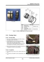
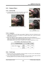
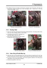
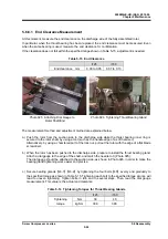
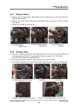
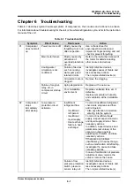
5.6.7 Balance
Piston
a) With the notch of balance piston
【
30
】
aligned with the slotted set screw of M rotor shaft
【
31
】
,
install the balance piston.
b) With the notch of the balance piston sleeve
【
33
】
aligned with the spring pin, install the balance
piston sleeve.
c) Install snap ring
【
32
】
and O-ring
【
35
】
.
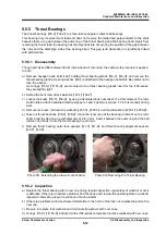
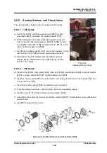
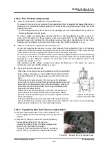
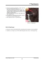
5.6.8 Bearing
Cover
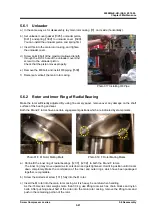
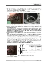
a) Screw two stud bolts symmetrically to the flange surface of the main rotor casing. Apply sufficient oil
to the flange surface (Photo 031), and then place bearing cover gasket
【
17
】
(Photo 032).
Take note that the gasket has right/left difference.
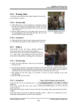
b) While using lifting tools, temporarily tighten bearing cover
【
16
】
with 4 bolts.
c) After driving the alignment pin in position (Photo 033), tighten the bolts and remove the lifting tools.
Photo 031 Applying Oil with Brush Photo 032
Photo 033
Photo 034
Temporarily Tightening Bolts Photo 035
Final Tightening with Torque Wrench
Photo 028 Installing
Balance Piston
Photo 029 Installing Balance
Piston Sleeve
Photo 030 Installing
Snap Ring


