
2200M4JE-HO-iS2-N_2014.04.
Chapter 5 Maintenance
Screw Compressor i-series
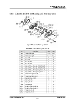
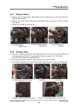
5.6 Reassembly
5-26
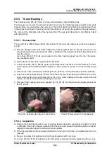
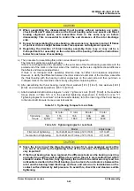
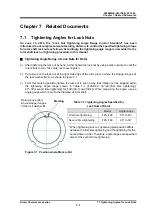
5.6.6.1 End Clearance Measurement
At this moment, measure the end clearance on the discharge side of the fully assembled rotor.
In particular, when the thrust bearing has been replaced, the end clearance must be measured. Even
when the same bearing is used, measure the end clearance for confirmation.
If the clearance does not fall within the specified range shown in Table 5-15, adjustment is needed.
Table 5-15
End Clearance
i125
i160
End clearance mm
0.03 to 0.05
0.07 to 0.13
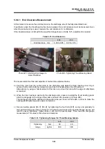
Photo 025
Attaching Dial Gauge to Photo 026
Tightening Thrust Bearing Gland
Rotor Shaft End
The measurement method and adjustment method are explained below.
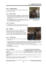
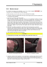
a) Push the rotor from the suction side to the discharge side while the thrust bearing inner ring is
secured to the rotor shaft, by using a tool (such as the handle edge of a soft hammer).
Alternatively, by using a chamfered part of the lock nut, pull out the rotor with the edge of a flat blade
screwdriver.
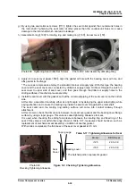
b) When the rotor has been pushed to the discharge side, prepare to install the thrust bearing gland.
Attach a dial gauge to the edge of the shaft, and match the needle to 0 (Photo 025).
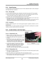
The dial gauge should be attached to the suction side, as shown in Photo 026, in order to make the
bearing gland tightening work easier and precise.
c) Secure bearing glands
【
43-1
】
【
43-2
】
by tightening the four bolts
【
45
】
evenly and gradually to
the specified torque as shown in Table 5-15. Tightening each bolt to the specified torque at once will
lead to uneven tightening. Tighten bolts in turn and in several steps. Then, read the dial gauge
measurement. This value is the actual end clearance.
Table 5-14
Tightening Torques for Thrust Bearing Glands
i125
i160
Tightening
torque
N·m 30
40
kgf·cm
300 390


