
2200M4JE-HO-iS2-N_2014.04.
Chapter 5 Maintenance
Screw Compressor i-series
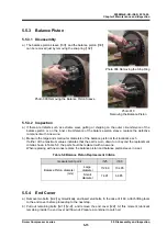
5.6 Reassembly
5-25
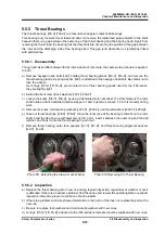
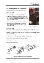
When assembling the disassembled thrust bearing without replacing any parts,
check the M and F stamp marks on the thrust bearing outer race spacer and thrust
bearing alignment spacer, and reassemble them in the same way as before
disassembly. This is essential to control the end clearance of the rotor discharge
side.
Even when assembling the same bearing, dimensions may become incorrect if flakes
of paint or dirt are caught between outer race spacers and alignment spacers.
Regarding the direction of thrust bearing assembly, there may or may not be a
V-shaped mark for assembly on the outer side of the bearing. Follow the instructions
below for each case of assembling.
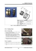
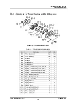
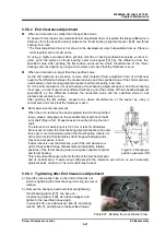
a) The procedure for assembling this portion is described in Figure 5-3.
The important points are explained below.
If there is a V-shaped mark for assembly on the outer side of the thrust bearing, assemble with the
pointed end of the mark on the inner side of the machine, as there is a slight directional difference
that affects end clearance adjustment.
If there is no V-shaped mark, assembly direction does not affect end clearance adjustment.
However, to clarify the difference between the inner side and outer side of the machine, assemble
the thrust bearing with the bearing number engravings on the outer side and then put down a
V-shaped mark on the machine's inner side by using blue sharpening stone.
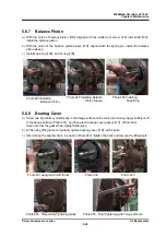
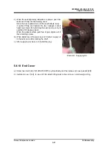
b) After assembling the thrust bearing, install thrust washers
【
41-1
】
【
41-2
】
, lock washers
【
40-1
】
【
40-2
】
and torsional slip washers
【
237-1
】
【
237-2
】
.
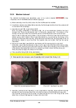
c) Attach dedicated shaft rotation stoppers 1 and 2. Tighten lock nuts
【
39-1
】
【
39-2
】
to the specified
torque shown in Table 5-13 or to the specified tightening angle shown in Table 5-14 (see "7.1
Tightening Angles for Lock Nuts" in this manual for details), to fix the inner ring of the thrust bearing
to the rotor shaft. Be sure to use a new lock washer.
Table 5-13
Tightening Torques for Lock Nuts
i125
i160
M rotor
F rotor
M rotor
F rotor
Tightening
torque
N·m
116
166
306
400
kgf·cm 1160
1660
3060
4000
Table 5-14
Tightening Angles for Lock Nuts
Model
Angle range
First turn of tightening
For both M and F rotors (i125 / i160)
30° to 40°
Second turn of tightening
For both M and F rotors (i125 / i160)
20° to 30°
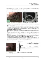
Since the inner ring of the thrust bearing is loose fit to ease assembly work at the
site, and is secured by the tightening force of the nut alone, the tightening work is
very important!
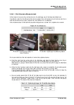
If the thrust bearing has been replaced, the difference between the bearing inner ring
and outer ring surfaces will be different even when the parts are manufactured within
standard values. Therefore, fully tightening the nut from the initial use may lead to a
noticeable reduction in the life of bearing, due to a lack of end clearance between the
rotor and the bearing head discharge end face, and also due to indentations on the
contact surface formed by ball pressure. To avoid this, check for end clearance while
tightening.


