2200M4JE-HO-iS2-N_2014.04.
Chapter 5 Maintenance and Inspection
Screw Compressor i-series
5.5 Disassembly and Inspection
5-17
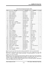
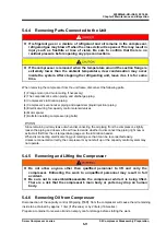
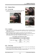
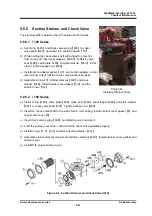
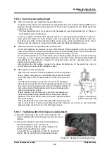
5.5.6 Bearing
Head
Though the case dividing method differs between i125 and i160,
the work flow is the same.
5.5.6.1 Disassembly
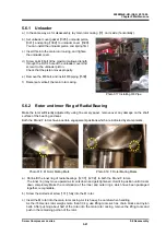
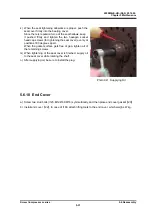
a) Attach lifting tools, remove all bolts
【
2-1
】
that hold the part to
the main rotor casing, and separate the part from the main
rotor casing. If bearing head gasket
【
12
】
is stuck, use a jack
bolt to remove it.
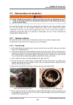
b) Remove bearing head
【
11
】
while taking care not to let it be
hit and damaged by the rotor shaft. Also take care not to let
the rotor fall off the main rotor casing.
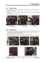
5.5.6.2 Inspection
a) If the alignment pin is bent or worn, replace it with a new one.
b) The bearing head gasket must be replaced with a new one.
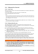
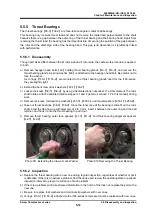
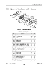
5.5.7 Rotors
Rotors
【
25
】
【
26
】
are heavy, precisely machined
components, which are the heart of the compressor.
Care must be taken not to get them damaged by dropping
or in other ways. Using damaged rotors may lead to
deterioration in performance or damage to the compressor.
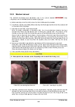
5.5.7.1 Disassembly
a) When using the i125-series, remove snap ring
【
29-3
】
from the F rotor.
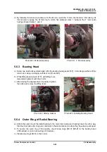
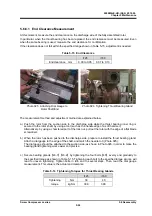
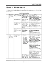
b) As it is heavy in weight, be careful when handling. As the i160-series rotor weighs more than 30 kg,
use lifting tools such as chain blocks and nylon belts. Pull out about two thirds of the rotor, attach a
belt around its outer circumference, and then pull out the remaining part of the rotor.
c) After pulling out the rotor, place it on V-blocks or the like to prevent damage to the outer
circumference.
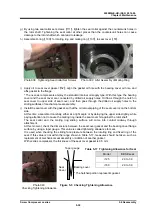
d) Remove slotted set screw
【
31
】
.
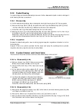
5.5.7.2 Inspection
Check that the rotor is not extremely worn or
damaged.
Rotors stay almost free from wear during
normal operation.
If the rotor is found worn, check the cause and review the operating state to preventrecurrenceof the
problem.
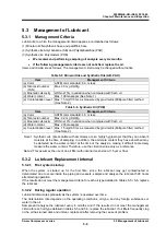
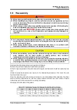
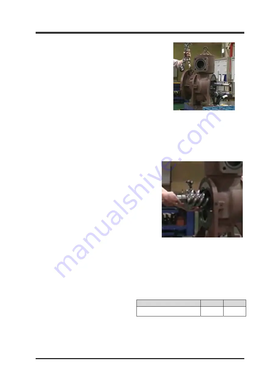
If the part wears beyond the replacement standard shown in Table 5-10, performance will be
deteriorated. Replacement of the rotor is recommended.
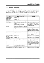
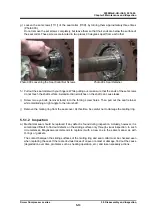
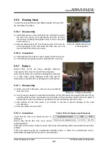
Photo 013 Attach Lifting Tools
to Bearing Head
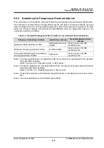
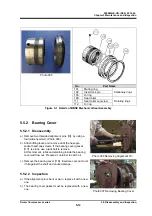
Photo 014 Pulling out the Rotor
measurement point
i125
i160
Rotor's outer diameter (mm)
127.475
163.175
Table 5-10 Rotor Replacement Standards


