
2202L5JE-DA-C5-N_2015.05.
5 Maintenance and Inspection
Compound 2-stage Screw Compressor
5.5
Reassembly
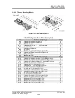
1612LSC Speed Increaser Type
5-52
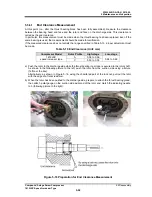
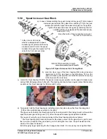
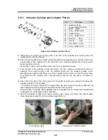
5.5.6.1
End Clearance Measurement
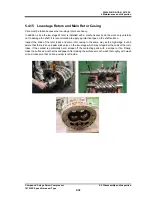
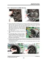
At this point (i.e., after the thrust bearing block has been fully assembled), measure the clearance
between the bearing head end face and the rotor end face on the discharge side. This clearance is
called as the end clearance.
In particular, this measurement must be made when the thrust bearing has been replaced. Even if the
same bearing is used, the measurement should be made for verification.
If the measured clearance does not satisfy the range specified in Table 5-10, proper adjustment must
be made.
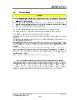
Table 5-10 End Clearance (Unit: mm)
Compressor Model
Rotor Profile
High-stage
Low-stage
1612LSC
speed increaser type
A
0.04 to 0.06
0.24 to 0.26
C
0.03 to 0.05
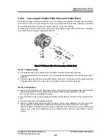
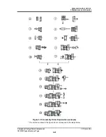
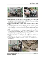
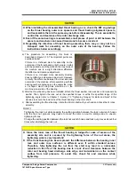
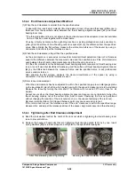
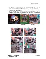
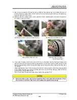
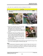
a) Push the rotor to the discharge side while the thrust bearing inner race is secured to the rotor shaft.
As shown in the following picture to the left, push the rotor from the suction side using a fixture
(Teflon or the like).
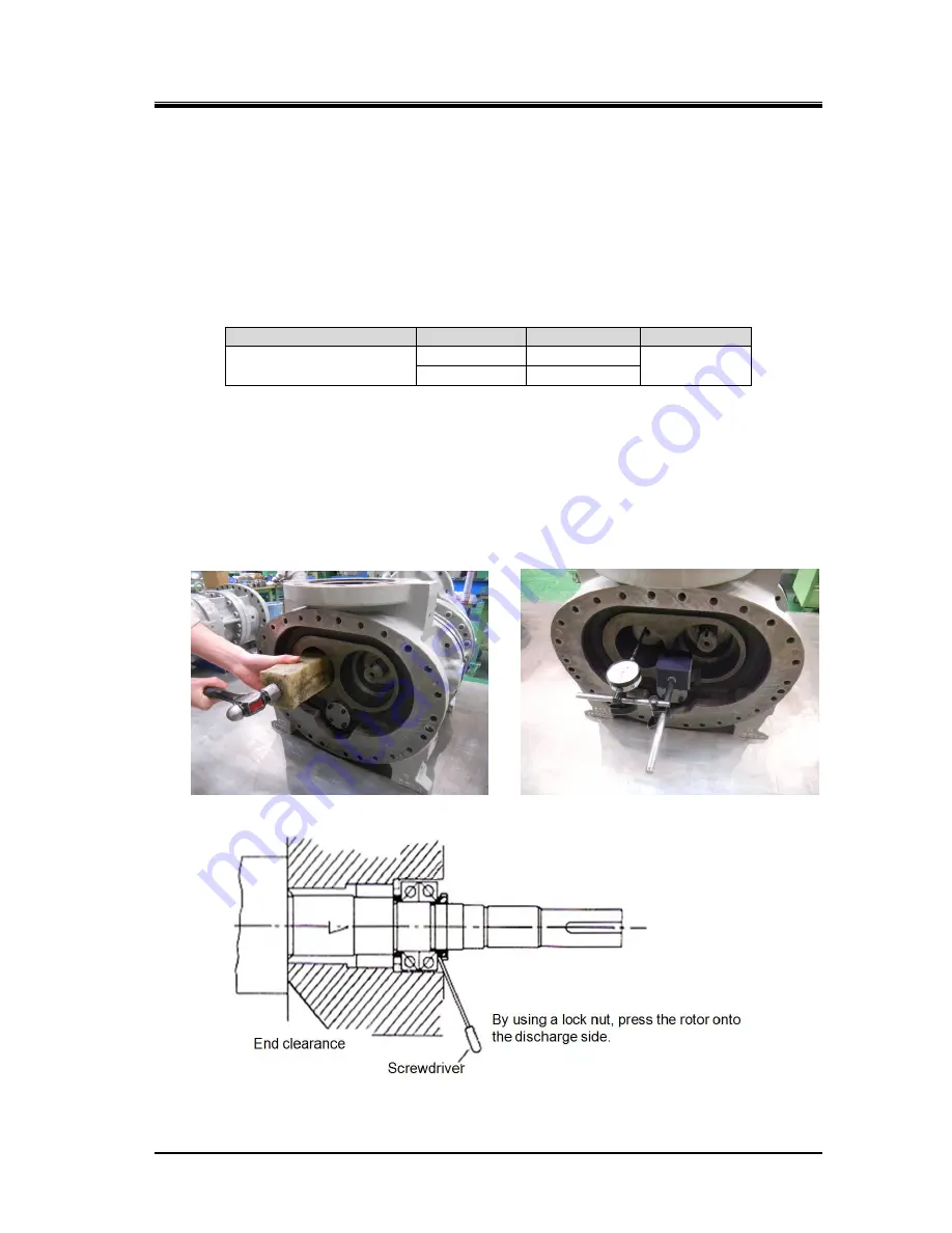
Alternatively, as shown in Figure 5-16, using the chamfered part of the lock nut, pull out the rotor
with the edge of a flat screwdriver.
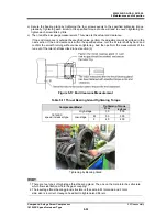
b) When the rotor has been pushed to the discharge side, prepare to attach the thrust bearing gland,
then attach a dial gauge on the suction side axial end of the rotor and match the indicating needle
to 0 (following picture to the right).
Figure 5-16 Preparation for End Clearance Measurement


