2202L5JE-DA-C5-N_2015.05.
5 Maintenance and Inspection
Compound 2-stage Screw Compressor
5.5
Reassembly
1612LSC Speed Increaser Type
5-62
g)
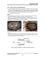
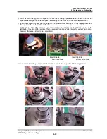
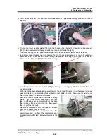
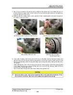
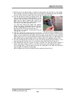
Bend the lock washer tooth into the notch of the lock nut to prevent loosening (following picture to
the left).
h)
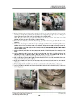
Tighten the thrust bearing gland [190] with the hexagon head bolts [191] inserting spring washers
[192] in turn and evenly to the specified torque (above picture to the right).
The thrust bearing for the speed increaser gear spindle receives both lateral and axial loads.
i) Install the speed increaser gear side bearing [183] to the speed increaser gear casing by using two
eye bolts. In this case, force the side bearing into position while aligning the notch in it with the
bearing anti-rotation pin [184] located in the casing.
j)
Turn the speed increaser gear spindle [188] by utilizing the coupling key [91] to check that there are
no abnormalities.
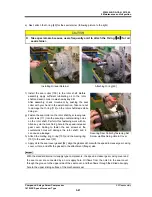
With the dial gauge probe applied against the mechanical seal fitting portion of the speed increaser
gear spindle, turn the spindle to check for axial runout (picture below). The amount of axial runout
must not exceed 0.03 mm with all models.
Excessive runout occurs when the thrust bearing
mark is not at the correct side, and it occurs if
fastening the lock nut performed without changing
the position of the lock nut wrench (i.e., the uneven
fastening of the lock nut).
Moreover small particles of dirt trapped between
parts may cause excessive runout.
Precise control of runout is important since the
performance and the life of the mechanical seal
are significantly affected if its amount exceeds the
limit.

