

2202L5JE-DA-C5-N_2015.05.
5 Maintenance and Inspection
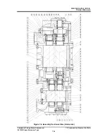
Compound 2-stage Screw Compressor
5.5
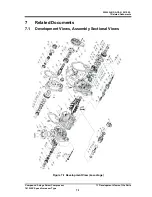
Reassembly
1612LSC Speed Increaser Type
5-71
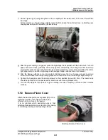
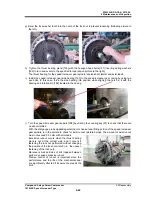
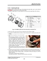
c) The micro-switch
【
125
】
is secured with two long phillips screws
【
126
】
. The micro-switch can be
removed by loosening these screws. Do not remove these screws except when the micro-switch
needs to be replaced. Leave them as they are when conducting inspections or positional
adjustments.
Inspection
a) Check that the wiring of the micro-switch has been removed. After that, turn the switch on and off
and check whether it works properly by using a circuit tester.
b) When the compressor's capacity control oil pressure pipe is opened due to overhaul or the like, pull
the unloader piston to the no-load position/full-load position by using nitrogen gas or compressed air
pressure, in order to check whether the micro-switch senses the 0 % and 100 % position of the
micro-switch cam.
c) In addition, conduct appearance check to find out any traces of water entry inside the indicator,
defects in the switch terminal such as corrosion, wear in the switch roller or micro-switch cam, etc.
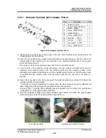
5.5.14.3
Assembly and Adjustment
a) Attach the micro switches. In theory, the switches will work on the cam irrelevant of the position of
the attachment holes. However, attach switches as close as possible to the cam.
b) Secure the potentiometer to the attaching board, attach the bevel gear, and secure with locking
screws.
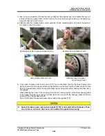
c) Press a spring pin into the potentiometer shaft hole.
d) Align the micro switch cam notch with the pin and attach to the potentiometer shaft.
e) Secure the potentiometer part to the support post [134].
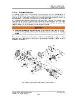
f) Attach the assembled part to the unloader cover using hexagon socket head cap screws [122].
Match the indicator cam shaft of the unloader cover with the micro switch cam.
Rotate the micro switch cam with your hand to check micro switch operation. (Make sure to use a
circuit tester etc.)
g) Align the countersinking holes of the shaft with the set screw of the micro switch cam and secure it.
This fixes the positions of the unloader slide valve, micro switch cam, and potentiometer.
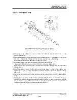
h) Attach the indicator cover. Electric wiring should be placed considering ease of operation.
i) Attach the indicator. If the dial needle is not set to 0 due to the alignment of the gears, remove the
indicator glass part, loosen the dial needle locking screw, and set the dial needle to 0. Assembly is
now complete.
When the position of the unloader piston is unknown
When the position of the unloader piston is unknown, position the indicator needle correctly by following
the procedure below.
a) When the compressor's capacity control oil pressure pipe is opened due to overhaul or the like, pull
the unloader piston to the no-load position by using nitrogen gas or compressed air pressure. Then,
align the indicator dial needle to the start point of the semicircular range drawn on the dial face, and
fix it. Next, move the unloader piston to the full-load position, and check that the indicator dial
needle points at the end point of the range drawn on the dial face.
b) In a normal state where the capacity control oil pressure pipe is not opened, move the unloader
piston by using a manual capacity control circuit. When the control power is turned on, keep the
indicator cover attached to avoid electrical shock. After the position of the piston is determined, turn
off the control power and conduct lockout/tagout. After that, remove the indicator cover and fix the
indicator dial needle.


