2202L5JE-DA-C5-N_2015.05.
3 Installation
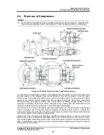
Compound 2stage Screw Compressor
3.2 Installation Works
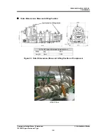
1612LSC Speed Increaser Type
3-5
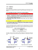
3.2.5 Installation
3.2.5.1 Installation
Check that the surface of the package unit for compressor installation is even and horizontal. If it is not
flat and horizontal, tightening the bolts may lead to compressor deformation, and operation may be
affected.
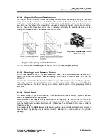
3.2.5.2 Shaft Alignment between Compressor and Driving Machine
Turn off the main power and control power of the driving machine before shaft
alignment work between the compressor and the driving machine. Be careful so that
the power of instruments does not turn on during shaft alignment work. If the power
turns on during shaft alignment work, the driving machine starts moving and there is a
risk of being entangled with the rotating shaft.
At the time of turning ON/OFF each electric power breaker, make sure to prevent
electric shock.
For shaft alignment work between the compressor and driving machine, use designated
tools in normal condition. If a worn or damaged tool or a tool unsuitable for the work is
used, there is a risk of being injured.
In the case shaft alignment between the compressor and the driving machine, be sure that the
deviations within the range shown in the Table 3–2. However, if alignment tolerance of the driving
machine side is more stringent than Table 3-2, please adjust to the request within the allowable value of
the driving machine side.
Table 3–2 Tolerance of Misalignment
Tolerance
Offset 6/100
mm
Angularity
3/100 mm (reference:
Φ
100 mm)
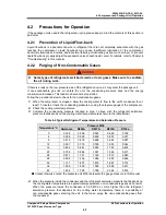
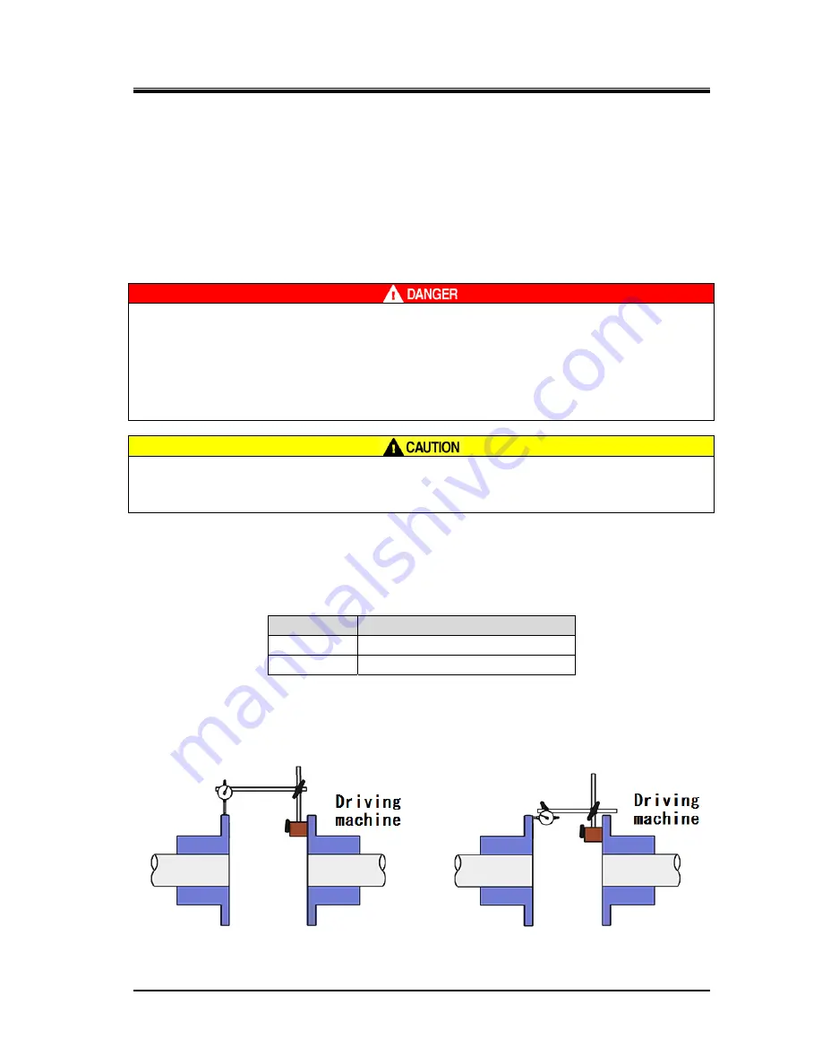
The Figure 3–3 and 3–4 show how to measure offset and angularity when performing the centering of
the shafts of the driving machine and this product using a dedicated hub, a dial gauge and a magnet
stand.
Figure 3-3 Measurement of Offset Figure 3-4 Measurement of Angularity