2202L5JE-DA-C5-N_2015.05.
5 Maintenance and Inspection
Compound 2-stage Screw Compressor
5.5
Reassembly
1612LSC Speed Increaser Type
5-53
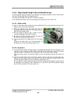
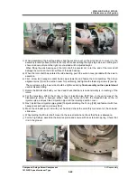
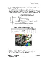
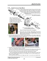
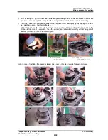
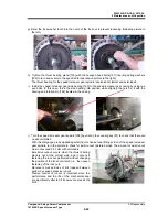
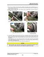
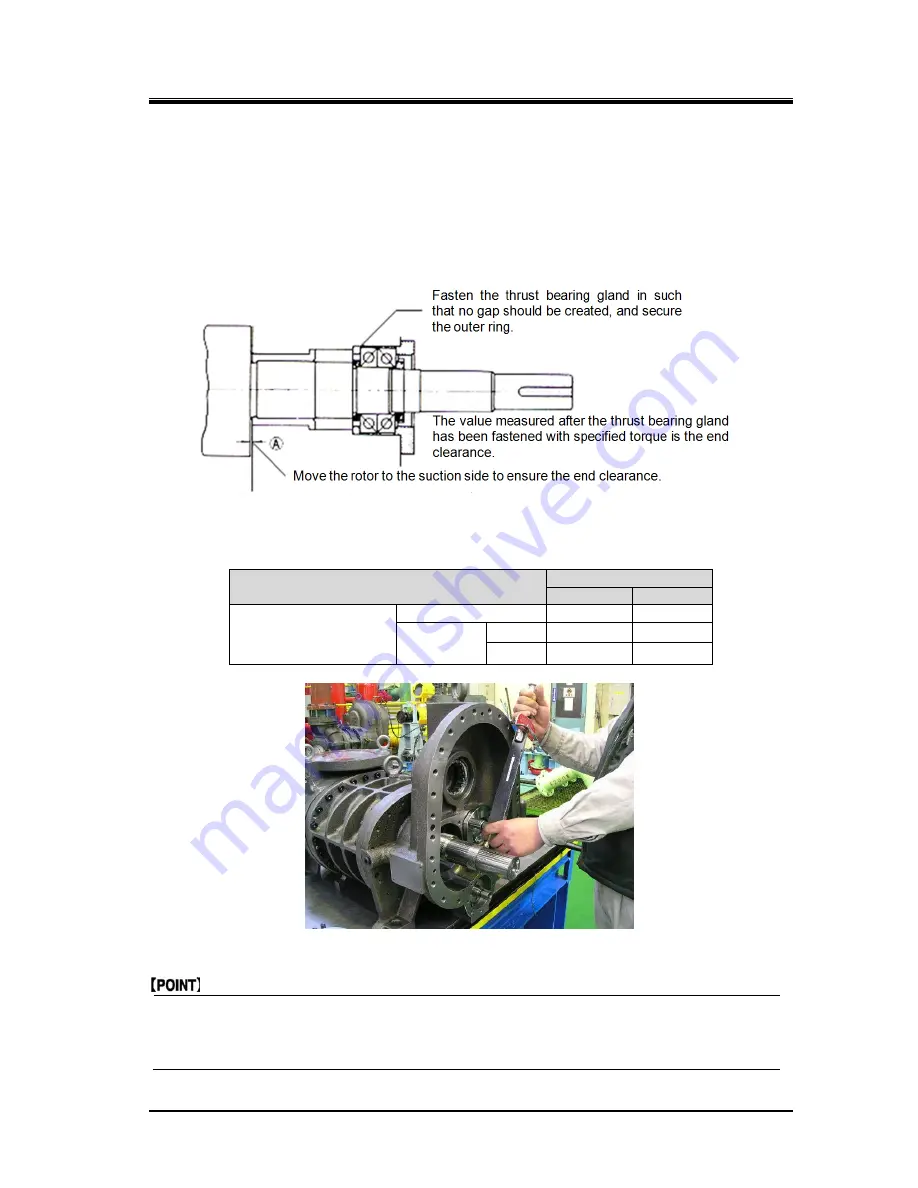
c) Secure the bearing gland by tightening the four screws evenly to the specified tightening torque
gradually. Tightening each screw to the specified torque at once will lead to uneven tightening so
tighten each screw little by little.
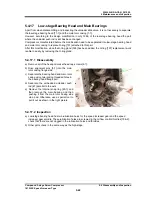
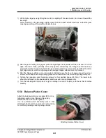
c) Then, read the dial gauge measurement. This value is the actual end clearance.
If the end clearance is outside the specified value, perform the adjustment work described in the
next section. If the end clearance is within the specified value, turn the M rotor shaft by hand and
confirm the smooth turning without uneven tightening. And then perform the measurement of the
run-out of the rotor shaft described in next section (3).
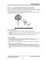
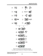
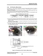
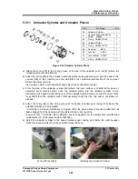
Figure 5-17 End Clearance Measurement
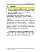
Table 5-11 Thrust Bearing Gland Tightening Torque
Compressor Model
Tightening Torque
N·m
kgf·cm
1612LSC
speed increaser type
High-stage 30
300
Low-stage
M 50 500
F 40 400
Tightening by Bearing Gland
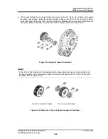
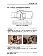
1. There are two types of high-stage thrust bearing gland. The one on the male rotor has structure
which flows lubrication oil into the gear coupling.
2. The low-stage thrust bearing gland, structure is the same in M rotor side and F rotor
side, size is incorrect. Hexagon head bolt to tighten also different.

