2202L5JE-DA-C5-N_2015.05.
5 Maintenance and Inspection
Compound 2-stage Screw Compressor
5.5
Reassembly
1612LSC Speed Increaser Type
5-48
5.5.5 Suction Cover and Side Bearings
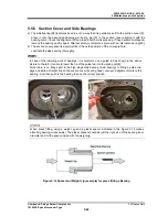
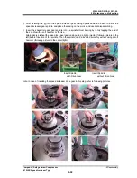
a) The side bearing [28] is dimensioned in such a way that it is gentle press-fit to the suction cover [5].
Press it onto the bearing positioning pin (spring pin) [8] in the suction cover aligning it with the
bearing notch. Check the alignment of the pin and notch while pressing. If they become misaligned,
remove the bearing and try again. After assembly is complete, secure with an internal snap ring [29].
b) The suction cover gasket is asymmetrical. Check the position of the oil supply hole.
Lubricate the side bearing thoroughly.
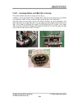
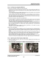
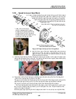
In case of the installing work of bearings, it is helpful to use a guide rod as shown in the above
picture to the left. It is able to insert the tip of the guide rod into the spring pin [8].
Since there is no flange part in the high-stage side bearing (main bearing) to fitting a guide rod,
align and write a straight line on the suction cover (bearing head), also put a alignment mark to the
bearing , and then push in the bearing to keep the correct position.
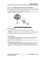
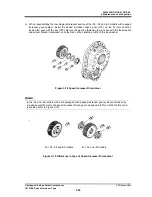
When press fitting, using a weight jig and a plastic spacer indicated in the Figure 5-14 makes
attaching bearing works easier. The plastic spacer should be just the right size of the bearing inner
diameter and hit the spacer inside with the weight jig.
Figure 5-14 Spacer and Weight Jig (example) for press fitting a Bearing

