2202L5JE-DA-C5-N_2015.05.
5 Maintenance and Inspection
Compound 2-stage Screw Compressor
5.4 Disassembly and Inspection
1612LSC Speed Increaser Type
5-37
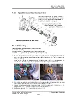
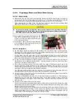
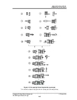
5.4.14 High-stage Rotors and Main Rotor Casing
5.4.14.1 Disassembly
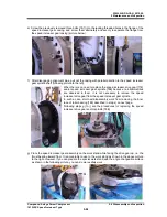
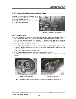
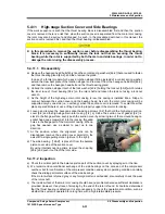
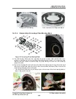
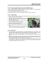
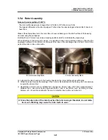
a) Either the M rotor or F rotor may be removed first. However, as the M rotor is longer, it is easier to
remove the M rotor first. When pulling out the M rotor (or F rotor) first, pull out about 2/3 of the full
length of the rotor by holding the shaft upward and turning it in the CW (or CCW) direction.
When approximately two thirds of the rotor has been pulled out, draw the rest out slowly while
attaching the other hand to the outer circumference of the rotor.
You should carefully note that the rotor must be rotated in the specified direction
while pulling it out. If the M (F) rotor is not turned during the pulling out process,
the F (M) rotor can also be pulled out together.
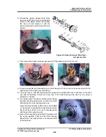
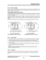
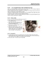
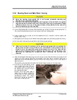
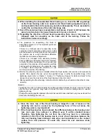
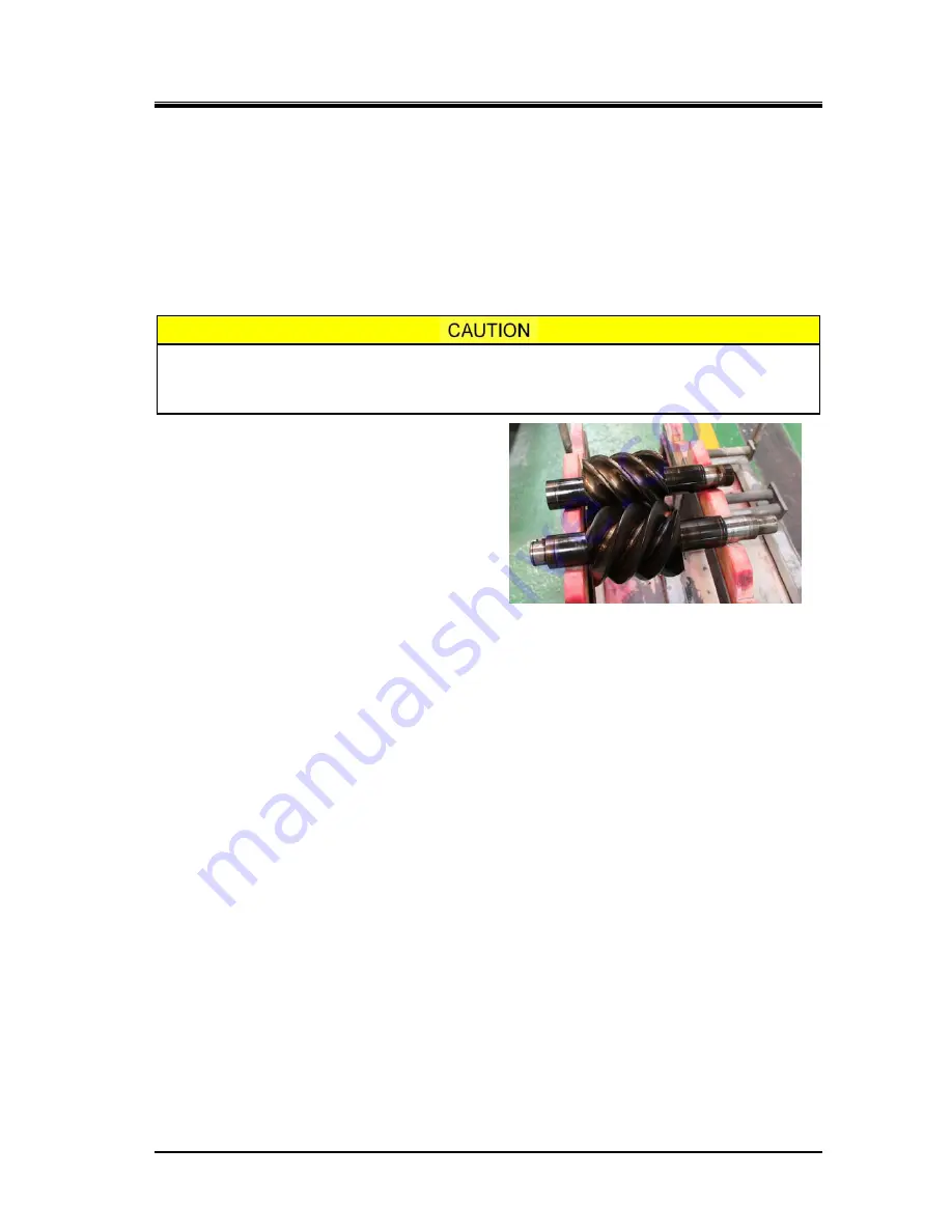
b) Do not place the removed rotor directly on the
floor. Use a cushion made of wood, etc., an
I-block or a V-block to suspend the bearing part
of the rotor (right picture).
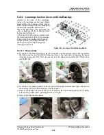
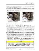
c) Pull out the F rotor in the same way. Take care
not to damage the main bearing with the end of
the rotor axis when removing.
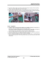
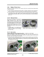
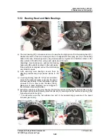
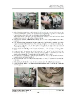
5.4.14.2 Inspection
a) No abnormality should be observed on the surface of the rotor lobes under normal operations.
Regarding the contact surface of the teeth, black luster should be seen on the root area of the M
rotor lobes and on the tip area of the F rotor lobes.
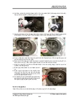
In other cases, when the suction gas or oil is contaminated by fine dust, there may be fine linear
scratches on the shaft surface, in the direction perpendicular to the shaft axis. If any such flaw is
found, use a fine sand paper or grindstone to smooth the surface.
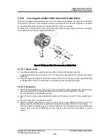
b) In case of ammonia refrigerant or gas compressor, the non-contact surface of the rotor may be
discolored by rust or deposits (above picture) . Use sand papers or others to finish the surface
according to the degree of the problem.
c) Then, check the bearing areas of the rotor shaft. Two types of finishing are used: one is the
induction hardening (polish finishing) for the standard specification, and the other is the hard
chrome plating (polish finishing), as a special specification. The most suitable finish is selected
according to the type of refrigerant and operation conditions.
Very little wear will be present unless the compressor is operated for a long time using dirty oil or
any hard matter is buried in the metal of the inner circumference of the bearing.
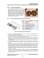
d) Check the portion of the shaft on which the thrust bearing is mounted for any trace to show that the
inner race of the bearing has rotated.
If the lock nut that fastens the inner race of the thrust bearing is loosened, or if the bearing is
abnormally worn, the inner race will become rotate. If any trace of rotation is seen, correct the
problem. Depending on the degree of the rotation trace, it might be necessary to replace the rotors
with new ones.
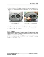
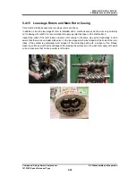
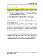
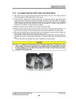
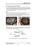
e) Check the inner surface of the main rotor casing.
There is a narrow clearance between the periphery of the rotor and the main rotor casing. Any slight
flaw present on the tip of the rotor teeth or on the inner surface of the main rotor casing, due to small
foreign matters, will not be a problem.
If there is any trace to show that the tips of the rotor teeth have hit the inner surface of the main rotor
casing, it is an abnormal condition. In such a case, the possible cause is that the main bearing
and/or side bearing is worn out. Take proper actions by finding the cause of the problem, such as
contamination of the lubricating oil or entrance of foreign matters.


