


Figure 2.5.1
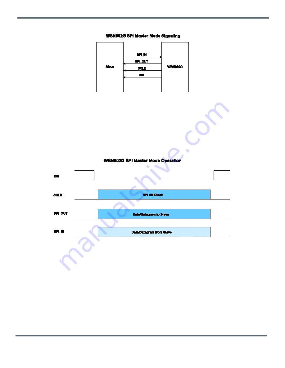
Figure 2.5.1 shows the signals a WSN802G uses in SPI Master mode. The AutoReport function triggers
the WSN802G module to clock out a configurable command string,
SPI_MasterCmdStr
, to collect data
from a Slave peripheral. The collected data is then transmitted as a data message. Alternatively, a host
connected to the base can transmit an SPI command as a data message to the remote. The WSN802G
will clock the command into its Slave peripheral and transmit back the Slave’s response, as show in Fig-
ure 2.5.2. In either case, data strings are limited to 256 bytes.
Figure 2.5.2
2.6 Analog I/O
The WSN802G includes two 10-bit ADC inputs, ADC0 (Pin 18) and ADC1 (Pin 19). Pin 25 provides a full-
scale reference voltage to support ratiometric ADC measurements. ADC measurements are triggered and
added to the automatic I/O report when a logic high signal is first applied to the WAKE_ IN pin or the
Au-
toReport
timer fires, as discussed in Section 2.2. An ADC reading is also made on the internal buss volt-
age of the WSN802G and included in the automatic I/O report. These readings can also be retrieved any-
time the WSN802G is in active mode using the IO_REPORT application protocol command as discussed
in Section 4.1.
The WSN802G also includes a 16-bit pulse width modulated output, PWM0 (Pin 9). The PWM output is
low-pass filtered to provide an analog output voltage with ripple suppressed to 7 bits. External low-pass
filtering can be added to further suppress ripple. The full-scale PWM output is referenced to the regulated
©2009-2015 by Murata Electronics N.A., Inc.
HN-210D/X, HN-214 D/X Rev. 2.0 01-16-15
Page 9 of 101
www.murata.com


