PEDAL FLANGER (MUTRON)
*The
Mutron
Flanger
that
this
build
was
modeled
after
had
a
120pf
capacitor
(C41)
and
a
10pf
capacitor
(C41A)
in
parallel
installed.
The
original
factory
schematic
depicts
a
single
120pf
capacitor.
After
reviewing
the
4046
data
sheet
and
researching
4046
clocks,
I
came
away
with
this
understanding.
The
4046’s
frequency
is
set
by
three
components.
A
timing
cap
across
pins
6
&
7,
a
resistor
from
pin
11
to
ground,
and
a
resistor
from
pin
12
to
ground
which
offsets
the
base
operating
frequency
set
by
the
other
two
components.
Increasing
the
capacitance
across
pins
6
&
7
will
decrease
the
frequency.
During
the
course
of
calibrating
the
flanger
prototype,
I
started
with
120pf
and
10pf
in
parallel.
I
was
unable
to
achieve
the
lower
range
of
50KHz.
I
found
that
an
additional
100pf
was
needed
to
achieve
50KHz
at
the
lower
end
of
the
clock
cycle.
There
are
images
of
a
Mutron
flanger
circuit
board
that
show
one
timing
cap
and
empty
holes
where
C41A
would
be
installed.
This
leads
me
to
conclude
that
the
actual
capacitance
for
the
timing
cap
should
be
chosen
at
the
time
of
calibration……if
needed
to
reach
the
lower
target
frequency
of
50KHz.
Summary of Contents for Pedal Flanger 3007
Page 5: ......
Page 6: ......
Page 7: ......
Page 8: ...PEDAL FLANGER MUTRON Main Board Overlay...
Page 10: ...5 32 in 6 50 in 134 5mm 164 7mm...
Page 11: ...111 6mm 4 41 in 3 54 in 89 9mm...
Page 18: ...4 5 6 1 2 3 9 8 7 4 5 6 1 2 3 SW2 SW1 PEDAL FLANGER MUTRON OFF BOARD WIRING LEGEND...
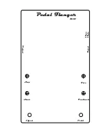
Page 34: ...Feedback Rate Start Stop Pedal Flanger 3007 Input Output Effect Pedal 12vac 18vdc...


