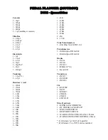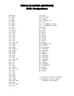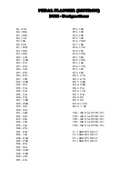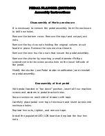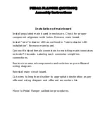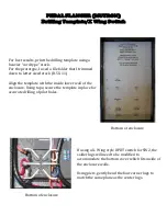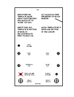
PEDAL FLANGER (MUTRON)
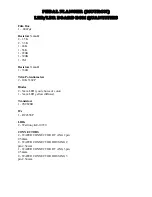
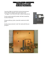
LED/LDR Board LED
Indicator Installation
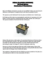
Insert the Effect In/Out (D14) and the Pedal indicator
(D15) LEDs through the outermost holes on the
“outriggers” trace side. (Flat side, cathode facing down)
On the component side, bend the led leads toward the
inside of the board.
Using needle nose pliers, insert the leads into the LED
pads,
On the component side, “work” the leads until they are
lying flat.
Summary of Contents for Pedal Flanger 3007
Page 5: ......
Page 6: ......
Page 7: ......
Page 8: ...PEDAL FLANGER MUTRON Main Board Overlay...
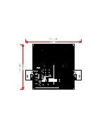
Page 10: ...5 32 in 6 50 in 134 5mm 164 7mm...
Page 11: ...111 6mm 4 41 in 3 54 in 89 9mm...
Page 18: ...4 5 6 1 2 3 9 8 7 4 5 6 1 2 3 SW2 SW1 PEDAL FLANGER MUTRON OFF BOARD WIRING LEGEND...
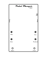
Page 34: ...Feedback Rate Start Stop Pedal Flanger 3007 Input Output Effect Pedal 12vac 18vdc...

