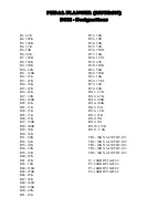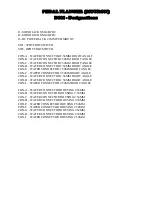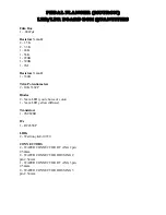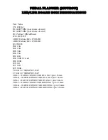
PEDAL FLANGER (MUTRON)
Assembly Instructions
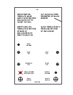
Disassembly of Morley enclosure
It is necessary to remove the pedal assembly from the enclosure
to drill new holes.
Remove the bottom cover. Remove the input and output jack
nuts.
Remove the four hex nuts holding the original volume circuit
board in place. Remove the volume circuit board.
Remove the next four hex nuts that secure the pedal assembly.
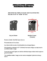
Remove the shutter by inserting a small diameter Phillips
screwdriver into the screw access hole on the lower left side of
the pedal.
Modify the shutter (see Pedal shutter modification) and reinstall
on pedal assembly.
Reassembly of foot pedal
With pedal bracket in “toe down” position, insert all four machine
screws and washers in pedal bracket holes.
Secure screws on each side of bracket with tape.
Carefully place pedal over top of enclosure and insert screws into
enclosure holes.
Replace hex nuts, tighten, and remove tape.
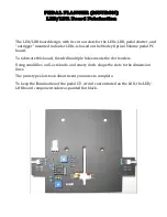
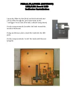
Install the populated LED/LDR board and replace the four hex
nuts.
Summary of Contents for Pedal Flanger 3007
Page 5: ......
Page 6: ......
Page 7: ......
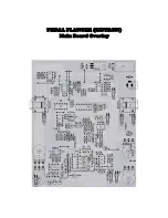
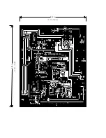
Page 8: ...PEDAL FLANGER MUTRON Main Board Overlay...
Page 10: ...5 32 in 6 50 in 134 5mm 164 7mm...
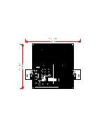
Page 11: ...111 6mm 4 41 in 3 54 in 89 9mm...
Page 18: ...4 5 6 1 2 3 9 8 7 4 5 6 1 2 3 SW2 SW1 PEDAL FLANGER MUTRON OFF BOARD WIRING LEGEND...
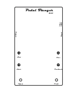
Page 34: ...Feedback Rate Start Stop Pedal Flanger 3007 Input Output Effect Pedal 12vac 18vdc...

