PEDAL FLANGER (MUTRON)
Test Point Fabrication
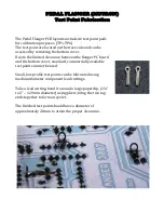
The Pedal Flanger PCB layouts include six test point pads
for calibration purposes. (TP1-TP6)
The test point are located on the trace side and can be
accessed by removing the bottom cover.
Due to the limited clearance between the flanger PC board
and the bottom cover, standard, commercially available
test points cannot be used.
Small, low profile test points can be fabricated using
medium diameter component lead cuttings.
Take a lead cutting, bend it around a large paperclip, (1¾”
to 2" – 1.19mm diameter) using pliers, bring the two tag
ends together to form an eyelet.
The finished test point should have a diameter of
approximately 2.8mm to attain the proper clearance.
Summary of Contents for Pedal Flanger 3007
Page 5: ......
Page 6: ......
Page 7: ......
Page 8: ...PEDAL FLANGER MUTRON Main Board Overlay...
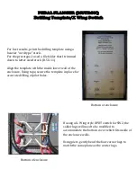
Page 10: ...5 32 in 6 50 in 134 5mm 164 7mm...
Page 11: ...111 6mm 4 41 in 3 54 in 89 9mm...
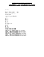
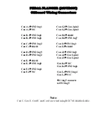
Page 18: ...4 5 6 1 2 3 9 8 7 4 5 6 1 2 3 SW2 SW1 PEDAL FLANGER MUTRON OFF BOARD WIRING LEGEND...
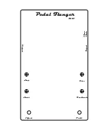
Page 34: ...Feedback Rate Start Stop Pedal Flanger 3007 Input Output Effect Pedal 12vac 18vdc...

