PEDAL FLANGER (MUTRON)
Assembly Instructions
Installation of main board
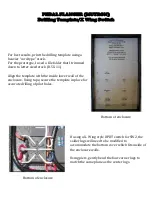
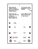
Install populated main board in enclosure. Check for proper
component alignment with holes. Remove main board.
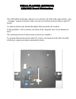
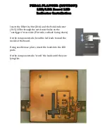
Install “rate” indicator LED as outlined in “rate indicator LED
installation”. Remove main board.
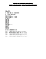
Connect finished female connectors to matching male connectors
on both PC boards. Labeling each connector simplifies
connections.
Route wires around components and switches as per offboard
wiring diagram.
Reinstall main circuit board.
Cut wires to length and solder to appropriate destination as per
offboard wiring diagram and offboard connectors list.
Move to Pedal Flanger calibration procedures.
Summary of Contents for Pedal Flanger 3007
Page 5: ......
Page 6: ......
Page 7: ......
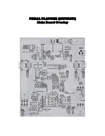
Page 8: ...PEDAL FLANGER MUTRON Main Board Overlay...
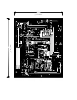
Page 10: ...5 32 in 6 50 in 134 5mm 164 7mm...
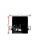
Page 11: ...111 6mm 4 41 in 3 54 in 89 9mm...
Page 18: ...4 5 6 1 2 3 9 8 7 4 5 6 1 2 3 SW2 SW1 PEDAL FLANGER MUTRON OFF BOARD WIRING LEGEND...
Page 34: ...Feedback Rate Start Stop Pedal Flanger 3007 Input Output Effect Pedal 12vac 18vdc...

