PEDAL FLANGER (MUTRON)
LED/LDR Board Fabrication
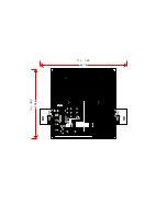
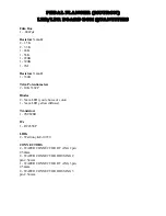
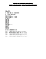
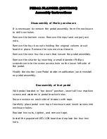
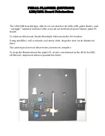
The LED/LDR board design, with its cut out slots for the LEDs, LDR, pedal shutter, and
“outrigger” mounted indicator LEDs, is based on the Morley Optical Volume pedal PC
board.
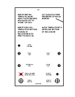
To fabricate this board, first drill multiple holes inside the slot borders.
Using small files, an X-acto knife, and emery cloth, shape the slots to the dimension
lines.
The prototype slots took about twenty minutes to complete.
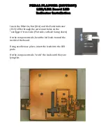
To keep the illumination of the pedal C.V. circuit concentrated on the LDR, the LED/
LDR board component side was painted flat black.
Summary of Contents for Pedal Flanger 3007
Page 5: ......
Page 6: ......
Page 7: ......
Page 8: ...PEDAL FLANGER MUTRON Main Board Overlay...
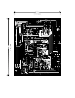
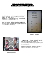
Page 10: ...5 32 in 6 50 in 134 5mm 164 7mm...
Page 11: ...111 6mm 4 41 in 3 54 in 89 9mm...
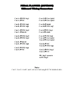
Page 18: ...4 5 6 1 2 3 9 8 7 4 5 6 1 2 3 SW2 SW1 PEDAL FLANGER MUTRON OFF BOARD WIRING LEGEND...
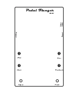
Page 34: ...Feedback Rate Start Stop Pedal Flanger 3007 Input Output Effect Pedal 12vac 18vdc...

