background image

Key Concepts

48

Landmark™ Test System Operation

Understanding the Control Loop

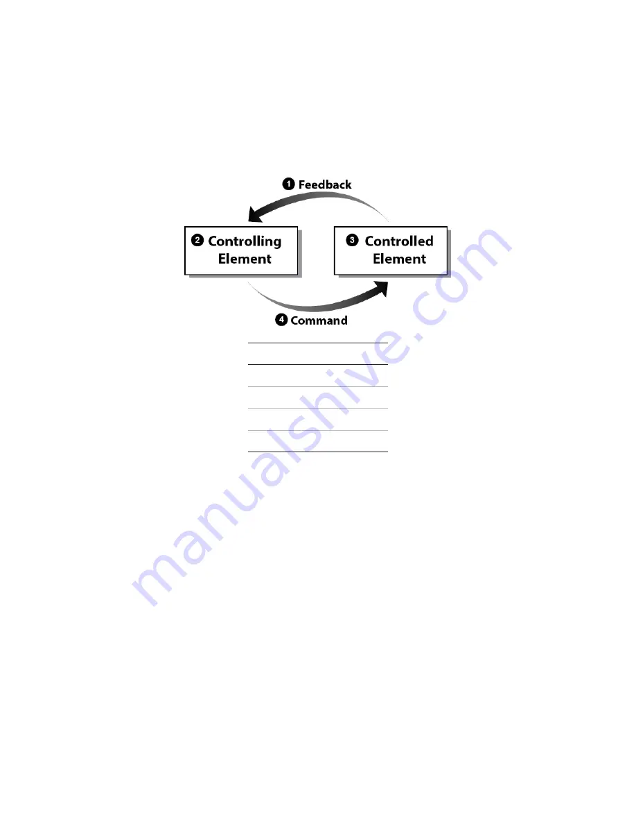
MTS Landmark Test Systems use closed-loop control, and understanding it lays a foundation for many
of the topics in this document. Closed-loop control is a basic servomechanism concept of controlling a
test, in which a controlling element controls a controlled element.

Closed Loop Control Concept

Item Description

1

Feedback

2

Controlling Element

3

Controlled Element

4

Command

The controlling element is the computer, the digital controller, and the MTS Station Manager
application. The controlling element produces a control signal (Command) that represents the
direction and amount of force the actuator should apply to the specimen. The controlled element
comprises the servovalve, the hydraulic actuator, and the specimen itself. The controlled element
applies the required forces (Command) to the specimen and the specimen reacts to it. The Feedback
is the response from one of various sensors that indicates how the controlled element has responded.

Closed Loop Control Step-by-Step

The following closed-loop diagram illustrates how the system operates when you use the Manual
Control panel in the Station Manager application to apply a compressive force to the specimen.
Assume that the system is in Force Control.

Summary of Contents for Landmark 370 Series

Page 1: ...MTS Landmark Test System Operation Using MTS FlexTest Controller Software and MTS TestSuite MPX Testing Software 100 275 889 C...

Page 2: ...ered or distributed without express written consent of MTS Software Verification and Validation MTS software is developed using established quality practices in accordance with the requirements detail...

Page 3: ...9 Identify system type 9 Be prepared to troubleshoot 9 Write down relevant information 9 After you call 10 Problem Submittal Form 10 Preface 11 Before You Begin 11 Safety first 11 Documentation Conve...

Page 4: ...oftware and the MTS TW Express application 43 Understanding MTS File Types 44 File Types 44 Creating and Modifying Parameter Sets 46 Selecting and Saving Parameter Sets 47 How MTS Files Work Together...

Page 5: ...Specimen Installation 64 Zero the Force Signal 66 Set Initial Tuning Parameters 67 Install the Specimen 70 Power up the Pump and HPU 70 Position the Actuator Using Displacement Control 71 Zero Displa...

Page 6: ...and Force Meters 101 If Appropriate Remove the Intact Specimen 102 If Appropriate Remove the Broken Specimen 105 Recover from a Tripped Limit 106 If Necessary Recover from a Tripped Force Limit 107 I...

Page 7: ...chsupport europe mts com Telephone Worldwide 1 800 328 2255 toll free in U S 1 952 937 4000 outside U S Europe 800 81002 222 International toll free in Europe Outside the U S For technical support out...

Page 8: ...l What is the controller model if applicable l What is the system configuration Know relevant computer information For a computer problem have the following information available l Manufacturer s name...

Page 9: ...as one of the following types l Electrodynamic material test system l Electromechanical material test system l Hydromechanical material test system l Vehicle test system l Vehicle component test syst...

Page 10: ...al Form Use the Problem Submittal Form to communicate problems with your software hardware manuals or service that are not resolved to your satisfaction through the technical support process The form...

Page 11: ...is specific to the activity to be performed Hazard notices immediately precede the step or procedure that may lead to an associated hazard Read all hazard notices carefully and follow all directions...

Page 12: ...ou should follow to a referenced item in the software Example Examples show specific scenarios relating to your product and appear with a shaded background Special terms The first occurrence of specia...

Page 13: ...Safety Landmark Test System Operation 13 Safety General Safety Practices 14 Safety Practices Before Operating the System 14 Safety Practices While Operating the System 19 Load Unit Hazard Labels 21...

Page 14: ...oves goggles and hearing protection Each test system operates within a unique environment which includes the following known variables l Facility variables facility variables include the structure atm...

Page 15: ...the power off Locate all hardware and software controls and know what their functions are and what adjustments they require If any control function or operating adjustment is not clear review the appl...

Page 16: ...kties shop aprons loose clothing or jewelry or long hair that could get caught in equipment and result in an injury Remove loose clothing or jewelry and restrain long hair Remove flammable fluids Remo...

Page 17: ...TS when in doubt about the safety or reliability of any system related procedure or modification that involves devices that contain any type of compressed gas Check bolt ratings and torques To ensure...

Page 18: ...any operating procedure write the change and the date of the change in the appropriate manual Provide test area guards Use protective guards such as cages enclosures and special laboratory layouts wh...

Page 19: ...as cages or shields and special laboratory layouts when you work with hazardous test specimens for example brittle or fragmenting materials or materials that are internally pressurized You must evalua...

Page 20: ...id long periods of work without adequate rest In addition avoid long periods of repetitious unvarying or monotonous work because these conditions can contribute to accidents and hazardous situations I...

Page 21: ...o not use RF transmitters Keep radio frequency RF transmitters away from the workstation computers remote terminals and electronics consoles Intense RF fields can cause erratic operation of the more s...

Page 22: ...e to follow operating instructions can cause death or serious injury Read and understand the operator s manual before using this machine Moving parts can crush and cut Keep hands clear while operating...

Page 23: ...e beyond rated working pressure can rupture components cause severe personal injury and damage equipment Do not exceed 21 MPa 3000 psi rated working pressure Hazard Label for HSM Needle Valve Adjustme...

Page 24: ...andmark Test System Operation Hazard Label for HSM Needle Valve Adjustment Icon Description The HSM needle valve is factory adjusted and should not be adjusted in the field except by MTS Field Service...

Page 25: ...oduction Landmark Test System Operation 25 System Introduction About This Manual 26 About Other MTS Documentation 26 System Overview 27 Load Frame Overview 28 Load Frame Controls Overview 29 Software...

Page 26: ...nstall calibrate set system preferences create test design files or perform other activities typically performed by Field Service Engineers Test Designers and Administrators About Other MTS Documentat...

Page 27: ...use of the MTS FlexTest Station Manager Application that is used for station setup 2 MTS TestSuite software MTS Multipurpose MP Express application MTS TestSuite Multipurpose MP Express software enabl...

Page 28: ...following illustration shows a typical load unit with common accessories Component Identification Load Frame Front and Rear View Item Component Description 1 Crosshead Moves up and down the columns to...

Page 29: ...e forces Other types of actuators are available such as rotary actuators 9 Servovalve Controls the rate and direction of hydraulic fluid to the actuator 10 Hydraulic Service Manifold HSM Controls the...

Page 30: ...essure adjust Adjusts the amount of hydraulic pressure to the grips The adjustment range is 1 21 MPa 100 3000 psi or 1 69 MPa 100 10 000 psi The highest pressure setting depends on the maximum pressur...

Page 31: ...tinued Software Overview Running a test on an MTS Landmark load frame system typically requires the use of the following two MTS software programs MTS FlexTest Series 793 Controller Software Operators...

Page 32: ...ing a Station Using the Open Station window you can select a configuration and a parameter set You can also select an interlock chain although it is common practice to select Interlock 1 Using the Mai...

Page 33: ...System Introduction Landmark Test System Operation 33 Setting Limits Setting limits helps prevent specimen damage and injury You can set limits using the Limits tab of the Station Setup window...

Page 34: ...ower sections of the main window are located together for convenience There you can reset or override interlock conditions as well as power up the hydraulic pump unit HPU and hydraulic service manifol...

Page 35: ...to compare the input signal to the feedback signal This activity is essential to setting tuning parameters and helps ensure good system response Using the Function Generator The function generator al...

Page 36: ...icon boxed in red found in the Station Setup window provides access to the tuning tabs You can enter tuning parameters on the Adjustments tab MTS TestSuite Test Software MTS Multipurpose MP Express A...

Page 37: ...ing a Report The MP application windows associated with each task are shown below Selecting a Test Selecting a test is done via the MTS TestSuite MP Express main window Setting Test Parameters Once th...

Page 38: ...k conditions powering up the HPU and HSM if necessary and pressing the Run button MTS TestSuite MP Express allows you to monitor the test using the tabs found in the main window Generating a Report Wh...

Page 39: ...System Introduction Landmark Test System Operation 39...

Page 40: ......

Page 41: ...8 Understanding Control Channels and Control Modes 50 Using Detectors and Actions to Protect Yourself and Your Equipment 50 Using the E Stop Control 51 Understanding the Load Train 51 Positioning the...

Page 42: ...ller software to set up your station l MTS TestSuite test software to run tests on your station MTS FlexTest Controller Software and the Station Manager Application MTS FlexTest software also referred...

Page 43: ...is the MTS Multipurpose MP Express applicationMTS Multipurpose MP Express application or MPX MPXMTS Multipurpose MP Express applicationfor short Note The MTS Multipurpose Elite application can be con...

Page 44: ...cation to load another specimen Then you minimize the Station Manager application maximize MPX start another test run and so on Switching Between Station Manager and MPX When Running Tests Item Descri...

Page 45: ...les and report templates are linked to tests with project settings MTS TestSuite projects are not associated with FlexTest projects Configuration Files A Station Configuration file cfg defines the con...

Page 46: ...ocedure Files Test Procedures files are similar to Test Template files but include a container that stores test data and results You can create a Test Procedure file from scratch or by selecting a Tes...

Page 47: ...sic workflow is as follows l You use the Station Manager application to open a Station Configuration l You select a Parameter Set which includes specific Sensor Calibration files for your Station Conf...

Page 48: ...er application The controlling element produces a control signal Command that represents the direction and amount of force the actuator should apply to the specimen The controlled element comprises th...

Page 49: ...ital controller generates this command and sends it to the servovalve The servovalve spool opens and allows more high pressure hydraulic fluid from the Hydraulic Power Supply to push on the actuator t...

Page 50: ...re Control Mode Example Suppose you want to compress your specimen using the Manual Command panel l If you choose force control the test system will apply a compressive force to your specimen in terms...

Page 51: ...re Testing After the specimen is installed and you are ready to run the test it is best practice to adjust the upper and lower force limit detectors to levels that will not interfere with forces that...

Page 52: ...tion 1 Force Sensor Load Cell 2 Spiral Washers 3 Upper Grip 4 Specimen 5 Lower Grip 6 Connector Stud 7 Actuator Positioning the Crosshead to Install the Specimen It is best practice to position the cr...

Page 53: ...e to the station The purpose is to ensure servoloop stability In this case you simply set tuning controls to conservative values Adjusting Values to Optimize Performance The second point is after you...

Page 54: ...gs are your window into the state of the system and your information center for the source of error conditions Each log entry is categorized with key words such as Warning and Error to inform you if i...

Page 55: ...on 55 Running the Example HCF Test About This Chapter 56 Test Procedure Overview 56 Prepare for Specimen Installation 57 Install the Specimen 70 Prepare to Run the Test 79 Run the Example HCF Test 93...

Page 56: ...ls included on the System Documentation CD that accompanies your system Test Procedure Overview The following is an abbreviated version of the complete Example HCF Force Test procedure You may find it...

Page 57: ...ge 100 5 Remove the Specimen A Remove Displacement Limits on page 101 B Switch to Running Max Min Displacement and Force Meters on page 101 C If Appropriate Remove the Intact Specimen on page 102 D If...

Page 58: ...er power switch is located on the back of the controller Open the Station Manager Application 1 Close any open applications on the computer desktop This prevents possible confusion from having multipl...

Page 59: ...on window select the controller for the station that you are using Note This window may not appear in all cases 5 Select a configuration and parameter set Under normal circumstances you would select a...

Page 60: ...for other stations and also leaves power to the hydraulic grips for specimen installation 7 Identify the current configuration and parameter set The configuration and parameter set currently in use is...

Page 61: ...the back This ensures that your configuration file matches your hardware and that you are able to collect valid data 2 Verify that the correct calibration file for the force sensor load cell is in use...

Page 62: ...n click the Delete button in the setup menu 3 Set up a Running Max Min Displacement Meter Use the following parameters l Meter Type Running Max Min l Channel Landmark 1 or other depending on your conf...

Page 63: ...Set up a Timed Displacement Meter Use the following parameters l Meter Type Timed l Channel Landkmark 1 or other depending on your configuration l Signal Displacement l Engineering Units mm A timed me...

Page 64: ...limits that control the amount of force read at the sensor However even with limits set do not rely solely on the force sensor to protect you from injury 1 Set the displacement limits to a wide range...

Page 65: ...ension Limit Note For this test MTS has determined that a setting of 5000 N will prevent damage to the system and the specimen Item Description 1 Type here and press Enter Note You must press Enter af...

Page 66: ...limit that adheres to your lab s specimen installation guidelines A Enter 50 N in the Lower Limit text box a negative number indicates compression Be sure to press Enter after typing in the limit B On...

Page 67: ...force meter Notice that the Manual Offset text box now shows the offset that was originally shown on the force meter 3 Reset meter history With the force signal zeroed resetting meter history for spec...

Page 68: ...g case sensitive when prompted 2 Set Displacement tuning parameters A Open the Tuning Landmark 1 Displacement window by selecting Station Manager Display Station Setup Channels Landmark 1 or other dep...

Page 69: ...the one you are setting up to run If you are unsure of what these initial settings should be contact MTS technical support 3 Set Force tuning parameters A Similarly open the Tuning Ch1 Force tab by se...

Page 70: ...Actuator Using Displacement Control on page 71 3 Zero Displacement on page 73 4 Clamp the Specimen in the Lower Grip on page 74 5 Position the Crosshead on page 76 6 Move the Specimen into the Upper...

Page 71: ...l interlock conditions will not reset until the pump is on 3 Power up the HPU hydraulic pump unit at the pump and on the screen if the HPU is shown Note HPU setups vary considerably by lab This docume...

Page 72: ...and that you have the necessary skill to proceed safely 1 Enable manual displacement control A In the Station Manager main window click the Manual Command button The Manual Controls window appears B...

Page 73: ...Note that the following controls can be adjusted by right clicking the slider control 3 Move the actuator to a point about 25 mm 1 in above the bottom of its travel A Using the slider slowly move the...

Page 74: ...tool to hold the specimen clamp the specimen in the lower grip using the controls on the MTS Landmark load frame You should position the specimen in the grip so that about 1 5th see the following pho...

Page 75: ...rease the force lower limit to a value that will allow clamping of the specimen in the upper grip B Select Station Manager Display Station Setup Channels Landmark 1 or other depending on your configur...

Page 76: ...he crosshead up or down so that there is about 25 mm 1 in clearance between the upper grip and the specimen B Once properly positioned reclamp with the crosshead lock control Move the Specimen into th...

Page 77: ...nce in force control the controller will follow your positioning commands while working to maintain the force that you specify in this case 0 N 1 In the Station Manager main window click the Manual Co...

Page 78: ...displacement limit See If Necessary Recover from a Tripped Force Limit on page 107 or If Necessary Recover from a Tripped Displacement Limit on page 110 Check and Reset Meter History Checking meter hi...

Page 79: ...ollowing steps 1 Perform Basic Performance Tuning on page 79 2 Switch to Peak Valley Meters on page 88 3 Adjust Limits for the Test on page 90 4 Show Station Manager Scope and Meters for the Test on p...

Page 80: ...button B Review the following parameters for this hard specimen test The following is a good place to start for this Example test with a hard specimen l P Gain 1 l I Gain 1 l D Gain 0 l F Gain 0 l FL...

Page 81: ...ce waveform using the following parameters l Channel Landmark 1 or other depending on your configuration l Control Mode Force l Command Type Cyclic l Target Setpoint 500 N l Amplitude 250 N l Frequenc...

Page 82: ...set up the scope as follows Y1 parameters l Channel Landmark 1 or other depending on your configuration l Signal Command l Unit N l Units div 100 l Offset 500 Y2 parameters l Channel Landmark 1 or ot...

Page 83: ...F Test Landmark Test System Operation 83 7 Run the Function Generator Click the Program Run button to apply the force waveform to the specimen If necessary clear any interlock conditions 8 Adjust P Ga...

Page 84: ...peration Correct P Gain Excessive P Gain A Open the Tuning Landmark 1 Force window found by selecting Station Manager Display Station Setup Channels Landmark 1 or other depending on your configuration...

Page 85: ...les of P gain found in the following displays If necessary adjust the P gain for the Force channel Note The Scope display shows how well the feedback signal is following the command signal You should...

Page 86: ...tion Generator button B Stop the Function Generator by clicking the Stop button and then change the wave shape from ramp to Sine C Click the Program Run button to run the sine wave Important Do not ad...

Page 87: ...rect I Gain Excessive I Gain A Navigate to the Tuning Landmark 1 Force window found by selecting Station Manager Display Station Setup Channels Landmark 1 or other depending on your configuration Forc...

Page 88: ...am Stop button to turn off the Function Generator Switch to Peak Valley Meters The Running Max Min meters served well during specimen installation however now that you will be applying a force wavefor...

Page 89: ...itivity is correct the meter will show minor fluctuations with meter updates no faster than the frequency A If you find the values in the Meters window changing at a rate less than the frequency of th...

Page 90: ...retain the wide displacement limit range set earlier because this example tension test uses no fixturing that requires protection A From the Station Manager main window select Display Station Setup a...

Page 91: ...he following parameters l Landmark 1 Force Upper Limit Upper Action 15000 N Interlock l Landmark 1 Force Lower Limit Lower Action 1000 N Interlock Show Station Manager Scope and Meters for the Test 1...

Page 92: ...on Manager The Station Manager application must be running underneath the MPX application in order to run tests Minimizing the Station Manager application clears the desktop while leaving it running f...

Page 93: ...can maximize Station Manager at any time by clicking the Station Manager button in the task bar Run the Example HCF Test 1 Running the example HCF high cycle fatigue test consists of the following st...

Page 94: ...stem Operation Open the MPX Application 1 Open the MTS Multipurpose MP Express application Select All Programs MTS TestSuite Multipurpose Express Select the Test 1 From the TestSuite main window selec...

Page 95: ...by selecting Example HCF Force Test Resources B If the MTS FlexTest resource names do not match resource error indicators will denote the validation errors Correct errors by making the MTS TestSuite n...

Page 96: ...HCF Test 96 Landmark Test System Operation 3 Review the status information Review the status information that appears If necessary use the Edit Parameters button to make corrections Otherwise click R...

Page 97: ...er panel reset the interlock if necessary B Power up the HPU and HSM by clicking the Power Low and Power High buttons in sequence Use the button in the lower right corner of the Power Panel to access...

Page 98: ...Example HCF Test 98 Landmark Test System Operation Review the Results 1 Review the test results At the conclusion of the test click any of the results tabs found in the MTS TestSuite main window for t...

Page 99: ...Running the Example HCF Test Landmark Test System Operation 99 Generate a Report 1 Generate a report...

Page 100: ...move the specimen so the test can be saved and the MPX application minimized 1 Save the test If desired save the test with a new name to preserve the original test 2 Minimize the TWX application Click...

Page 101: ...select Display Station Setup and click the Channel Input Signals button B Select the Displacement channel C Select the Limits tab D Set the Displacement Upper Action and Lower Action to Disabled Swit...

Page 102: ...ers to Running Max Min Meters to monitor history during specimen removal A In the Station Manager application main window click the Meters button B Click in the title bar of each Peak Valley meter and...

Page 103: ...n the Manual Cmd text box and press Enter 3 Switch to Displacement control mode This prevents unwanted movement of the actuator A In the Station Manager application main window click the Manual Contro...

Page 104: ...to open the Manual Command window B Select the following parameters l Channel Landmark 1 or other depending on your configuration l Control Mode Displacement l Enable Manual Command Checked C Using th...

Page 105: ...uator grasp the specimen and release the lower grip That completes this Example test If Appropriate Remove the Broken Specimen Use this procedure only if the specimen is broken at the conclusion of th...

Page 106: ...Checked C Using the slider control slowly retract the actuator until you have enough clearance to remove the specimen halves 3 Ensure that the HSM is off The HSM should have turned off when the displa...

Page 107: ...ed l Your test limits may not have been set high enough l The specimen may break resulting in the end of the test Rather than cover all possibilities this section addresses the first case only Adapt t...

Page 108: ...eset the interlock B Select Station Manager Display Station Setup Channels Landmark 1 or other depending on your configuration Force C Click the Channel Input Signals button to display the Inputs Land...

Page 109: ...he Power Low button and then the Power High button for the HPU and HSM 5 Reset Force control to zero In the Station Manager application main window click the Manual Control button In the Manual Contro...

Page 110: ...configuration Force Limits B Enter 50 N in the Lower Limit text box and ensure that Interlock is selected for the Action 8 Release the upper grip Using the controls on the load frame release the uppe...

Page 111: ...recover from other situations 1 Check current displacement limits A In the Station Manager application main window select Display Station Setup Displacement Channel Input Signals B Select the Limits t...

Page 112: ...o override the Interlock for 21 seconds and then power up the HPU and HSM 4 Warning Do not move the control slider until the crush zone is clear and you can monitor actuator movement Unskilled movemen...

Page 113: ...System Operation 113 5 Move the actuator to within acceptable displacement limits In the Station Manager application main window click the Manual Control button Move the actuator to within acceptable...

Page 114: ......

Page 115: ...Maintenance Landmark Test System Operation 115 Maintenance Routine Maintenance Overview Checklist 116 Maintenance Intervals 119 Daily Inspections 120...

Page 116: ...fts Supports MTS 2 MTS MTS MTS MTS Lift Seal Condition is Dry MTS MTS MTS MTS MTS Lock Seal Condition is Dry MTS MTS MTS MTS MTS Crosshead Columns are Clean MTS MTS MTS MTS MTS Column Abrasions are Ac...

Page 117: ...1 MTS Actuator Cursory Check of Actuator MTS MTS MTS MTS Actuator Area is Dry MTS MTS MTS MTS Actuator Platen Area is Clean MTS MTS MTS MTS Piston Rod Wear is Acceptable MTS MTS MTS MTS Bionix Lubrica...

Page 118: ...Change Filters MTS Low Pressure Adjustment Model 294 MTS Hoses Cables Cursory Check of Hoses Cables Connectors MTS MTS MTS MTS Absence of Hose Abrasions Blisters Vulcanizing MTS MTS MTS MTS Cable Con...

Page 119: ...TS MTS Grip Action is Acceptable MTS MTS MTS MTS Lubricate Grip Inserts MTS MTS MTS MTS Recommended service to be performed at each running time interval noted continued Maintenance Intervals The foll...

Page 120: ...formance has deteriorated Perform 252 Servovalve maintenance adjust mechanical null After the valve balancing procedure electrical compensation has been completed and the results are judged unsatisfac...

Page 121: ...m Operation 121 l Hoses must be routed as to avoid direct heat sources moving or abrasive equipment l Check actuator speed control functionality If any problems are encountered they should be repaired...

Page 122: ......

Page 123: ...Decommissioning Landmark Test System Operation 123 Decommissioning Decommission 124...

Page 124: ...tting to release all pressure from the grips and hoses Turn off the Model 685 Grip Control and disconnect electrical power Remove the hoses If the unit has an integrated grip control Model 318 and MTS...

Page 125: ...re removing the component Cap each hose port and hardline component 12 Dispose of all hydraulic fluid in accordance with all local codes regarding hazardous materials handling and disposal 13 Disconne...

Page 126: ...Decommissioning 126 Landmark Test System Operation B Floorstanding controllers can be lifted onto a suitable cart and moved to a desired location...

Page 127: ...60 control channels 50 closed loop 48 displacement 50 Emergency Stop E Stop 51 exclusive 66 force 50 Manual Command slider 72 manual displacement 72 modes 50 103 module grip 29 load frame 29 signal 48...

Page 128: ...0 releasing 103 105 106 110 upper 52 H hazard labels 21 hoses maintaining 118 HPU hydraulic power unit powering up 71 HSM hydraulic service manifold 29 maintaining 117 turning off 60 104 hydraulic ser...

Page 129: ...7 31 42 configuration files 45 project files 45 sensor calibration files 46 MTS Multipurpose MP Express application 27 31 opening 94 project files 45 typical tasks 36 MTS TestSuite software 27 42 O of...

Page 130: ...105 removing intact 102 Station Manager application 27 set up activities 42 typical tasks 31 status information 96 stop emergency 31 support phone 9 technical 7 switch actuator velocity limiting 31 sy...

Page 131: ...Index Landmark Test System Operation 131 Z zero sensor Auto Offset 73 sensor see Auto Offset 67...

Page 132: ......

Page 133: ......

Page 134: ...MTS Systems Corporation 14000 Technology Drive Eden Prairie MN 55344 2290 USA Email info mts com www mts com ISO 9001 Certified Quality Management System...

Reviews: