27
Installation
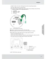
(6) Tighten screws on connector and tug gently on wires to ensure they are secure.
(7) Connect shield of cable to the ground screw.
(8) Connect an XCell or XIR PLUS sensor using the green connector. Sensor wires are already
connected as shown on the cover plate (see Fig. 21):
a. +DC (RED)
b. RS485 Com + (GRN)
c. RS485 Com - (BLU)
d. -DC (WHT)
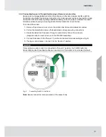
Fig. 21
Connecting a Sensor to the Board
Note:
Sensor connectors come pre-wired on the sensor body.
Note:
Leaving exposed wire from the connector can electrically short the system.
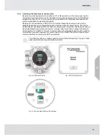
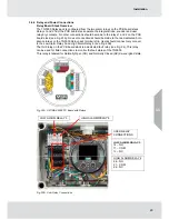
TG5000 without power supply option power and analog output connections.
(1) Remove the TG5000 enclosure cover.
(2) Use a small, flat head screwdriver to open the power and analog wire entries on the TB1.
(3) Connect the power and analog output connections (see Fig 20B).
Fig. 20B TG5000 without power supply
US
Summary of Contents for TG5000
Page 1: ...Operating Manual TG5000 Gas Monitor Order No 10212126 L Y REV 0 US ...
Page 36: ...36 Operation US ...
Page 46: ...46 Operation US ...
Page 62: ...62 Maintenance US ...
Page 63: ...63 Maintenance US ...
Page 64: ...64 Maintenance US ...
Page 70: ...70 Appendix Calibration Guide and Additional Gases US ...
Page 71: ...71 Appendix Calibration Guide and Additional Gases R 32 US ...
Page 72: ...72 Appendix Calibration Guide and Additional Gases US ...
Page 75: ...For local MSA contacts please visit us at MSAsafety com ...

