


18
Installation
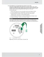
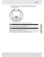
6. Verify the sensor connector is firmly seated on the terminal board.
7. Attach the sensor's ground to either of the grounding screws inside the TG5000 back plate.
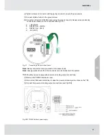
8. Replace the board stack legs into the four depressions in the mounting plate. Push firmly
on the board stack where indicated (see Fig. 10).
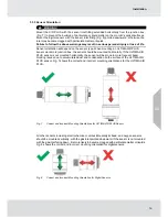
Fig. 10
Highlighted Areas Show Where to Press when Replacing a Board Stack
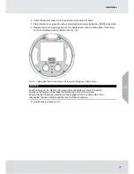
NOTICE
Avoid pressing on the left and right areas where the LEDs are located. Pressing
directly on the display will damage the display and will void the warranty.
Ensure that the electronics assembly is fully engaged in the mounting holes. If not
fully seated, the user interface buttons may not function properly.
9. Replace the enclosure cover.
US
Summary of Contents for TG5000
Page 1: ...Operating Manual TG5000 Gas Monitor Order No 10212126 L Y REV 0 US ...
Page 36: ...36 Operation US ...
Page 46: ...46 Operation US ...
Page 62: ...62 Maintenance US ...
Page 63: ...63 Maintenance US ...
Page 64: ...64 Maintenance US ...
Page 70: ...70 Appendix Calibration Guide and Additional Gases US ...
Page 71: ...71 Appendix Calibration Guide and Additional Gases R 32 US ...
Page 72: ...72 Appendix Calibration Guide and Additional Gases US ...
Page 75: ...For local MSA contacts please visit us at MSAsafety com ...


