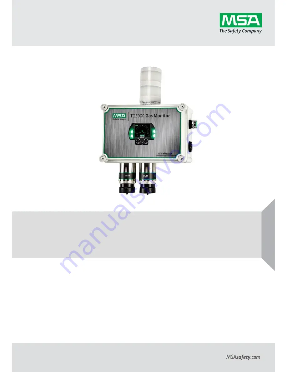
background image


Operating Manual 

TG5000® 

Gas Monitor 


Order No.: 10212126  

(L)-Y REV. 0  


US


Summary of Contents for TG5000

Page 1: ...Operating Manual TG5000 Gas Monitor Order No 10212126 L Y REV 0 US ...

Page 2: ...1000 Cranberry Woods Drive Cranberry Township PA 16066 USA Phone 1 800 MSA 2222 Fax 1 800 967 0398 For your local MSA contacts please go to our website www MSAsafety com MSA 2020 All rights reserved US ...

Page 3: ...tation 16 3 3 4 Connecting Sensor to Transmitter Housing or Remote Junction Box 17 3 3 5 Integrated Mounting Points 19 3 3 6 Installing a Remote Sensor Junction Box 20 3 3 7 2 50 8 mm Pipe Mount 21 3 3 8 Adjustable Pipe Mount 21 3 3 9 Duct Mount 22 3 3 10 Mounting with an SM5000 Sampling Module 23 3 4 Electrical Power Connections 24 3 4 1 Electrical Warnings Read before Connecting Power 24 3 4 2 E...

Page 4: ...w to Calibrate XCell Sensor 55 5 8 How to Calibrate an Oxygen XCell Sensor 56 5 9 How to Calibrate an XIR PLUS Sensor 56 5 10 XCell Catalytic Bead LOC Over Range 56 5 11 Calibration Confirmation and AS Found AS Left Values 56 6 Maintenance 57 6 1 ULTIMA XIR PLUS Cleaning Procedure 57 6 2 Replacing an XCell Sensor 58 6 3 Clearing a Blockage 60 6 4 Troubleshooting 61 7 Ordering Information 66 7 1 Re...

Page 5: ...itoring perfor mance alter flameproof explosion proof characteristics or void agency approvals Failure to follow the above warnings can result in serious personal injury or loss of life This device complies with Part 15 of the FCC Rules Operation is subject to the following two conditions device may not cause harmful interference and device must accept any interference received including interfere...

Page 6: ... if the warranty claim results from physical abuse or misuse of the product No agent employee or representative of the Seller has any authority to bind the Seller to any affirmation representation or warranty concerning this product Seller makes no warranty concerning components or accessories not manufactured by the Seller but will pass on to the Purchaser all warranties of manufacturers of such ...

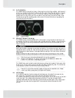
Page 7: ...s which require a countdown Fig 1 OLED Display In addition to the OLED display the TG5000 also employs green yellow and red LEDs on the side and lower middle of its face These are used to signal normal operating conditions fault conditions and alarm conditions The TG5000 will go into Eco Mode after 3 minutes of no interaction and if not in an alarm condition While in Eco Mode the main display will...

Page 8: ...ed devices Take appropriate precautions in the event a loss of wireless signal occurs Failure to follow the above warning can result in serious personal injury or loss of life If the device was not ordered with Bluetooth it cannot be upgraded If ordered with Bluetooth the device will be shipped with Bluetooth enabled See section 4 for instructions on disabling Bluetooth The TG5000 and user provide...

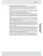
Page 9: ...napshots provided by the pulse check to adjust sensor output compen sating for environmental impacts on sensor accuracy If the AEC adjustment is greater than expected based on typical environmental impact variations the transmitter LED s will slowly flash GREEN alerting users that the sensor should be calibrated to reset the AEC cycle Users can also enable a Calibration Alert function that will se...

Page 10: ...of the SafeSwap feature communications protocol or functions provided by the software of this instrument or of the communications apparatus and software connected to this instrument Follow the warnings below when removing or replacing sensors Never remove or replace a Sensor Body Assembly or an Ultima XIR Plus while under power or when explosive hazards are present Confirm that the area is free of...

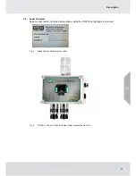
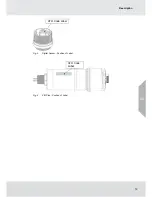
Page 11: ... 2 9 Label Overview System serial number is located where shown inside the TG5000 lid highlighted in yellow Fig 3 Blank System Serial Number Label Fig 4 TG5000 Position of Serial Number Label Located Inside of Lid US ...

Page 12: ...12 Description Fig 5 Digital Sensor Position of Label Fig 6 XIR Plus Position of Label US ATO Code Label ATO Code Label ...

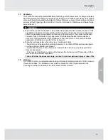
Page 13: ...r Body Assembly or an Ultima XIR Plus while under power or when explosive hazards are present Confirm that the area is free of explosive hazards before removing or replacing an XCell Sensor under power To remove an XCell Sensor unscrew XCell Sensor three full turns wait 10 seconds and then remove the XCell Sensor completely Do not paint the device Avoid painting in areas where the TG5000 and remot...

Page 14: ...mine mounting hardware requirements Review approvals and ensure suitability for installation Mounting For XP remote s attach appropriate sensor to the junction box see section 3 3 3 for proper sensor orientation For GP remote s the sensor already comes attached see section 3 3 3 for proper sensor orientation Mount transmitter or junction box using appropriate mounting hardware Confirm free air flo...

Page 15: ...ed When the best sensor place ment would not allow the transmitter display to be easily viewed or accessed a remote junction box can be used to mount the sensor remotely from the transmitter allowing both to be installed in the optimum location Two main factors should be considered when choosing a sensor location The first is the density of the target gas relative to the air Gases such as propane ...

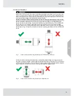
Page 16: ...ted horizontally If the ULTIMA XIR PLUS sensor is not mounted horizontally the sensor will be prone to more frequent beam blocking issues due to accumulated dust and condensation on the surface of the ULTIMA XIR PLUS sensor Fig 7 shows the correct and incorrect mounting orientations for the ULTIMA XIR PLUS Fig 7 Correct and Incorrect Mounting Orientations for ULTIMA XIR PLUS Sensor All other senso...

Page 17: ...urn the junction box lid counterclockwise to remove 2 Pull on the metal bail to remove the board stack and expose wiring connections 3 Route the cable from the sensor through a conduit entry hole in the enclosure Repeat to attach a second sensor to the TG5000 transmitter 4 Connect the sensor to the Sensor 1 position on the electronics assembly see Fig 9 5 If using a second sensor connect it to the...

Page 18: ...mly on the board stack where indicated see Fig 10 Fig 10 Highlighted Areas Show Where to Press when Replacing a Board Stack NOTICE Avoid pressing on the left and right areas where the LEDs are located Pressing directly on the display will damage the display and will void the warranty Ensure that the electronics assembly is fully engaged in the mounting holes If not fully seated the user interface ...

Page 19: ... TG5000 transmitter can be mounted withorwithout any additional brackets using the integrated mounting holes Clearance holes for 10 32 screws see Fig 11A for mounting hole location Fig 11A Internal Mounting Holes Fig 11B Mounting Bracket Optional US ...

Page 20: ...ted within maximum distance from the power supply see Ultima X5000 Gas Monitor Manual P N 10177361 for wire lengths The junction box does not have an illuminated display and has two connectors a single sensor input and an output connecting to the transmitter A 16 AWG 1 31mm2 4 element cable with a braided shield should be used for the electrical connection between the junction box and the TG5000 t...

Page 21: ... 2 50 8 mm pipe U bolt rated for the weight and dimensions of the housing can be used Fig 14 2 Pipe Mount with U Bolt 3 3 8 XP Remote Sensor Adjustable Pipe Mount A Universal Pipe Mount Kit Part Number 10176946 can be used to mount the remote sensor housing on pipes ranging from 1 6 20 150 mm in diameter Two brackets are mounted over top of the integrated mounting tabs and fitted with an adjustabl...

Page 22: ...24 and large ducts 20 40 508 1016 mm in diameter Part Number 10179321 The flat duct mount Part Number 10176947 is universal for flat ducts NOTICE Consider the sensor type before choosing a duct mount location ULTIMA XIR Plus sensors should be mounted horizontally and all other sensors should be mounted vertically NOTICE Air flow in the duct must be zero to ensure proper calibration Fig 16 Flat Duc...

Page 23: ...N 10043264 model are available for use with the TG5000 with either digital or XIR sensors For more information on mounting requirements and use with SM5000 sampling modules see the SM5000 operating manual s Fig 18 Mounting the SM5000 with Digital Sensor Fig 19 Mounting the SM5000 with XIR PLUS Sensor US ...

Page 24: ...nit that prevents water incursion The internal grounding terminal located in the base of the transmitter enclosure must be used for equipment grounding The external grounding terminal is only to be used as a supplemental bonding connection where local authorities permit or require such a connection As part of the product certification it was verified that optional communication functions of this g...

Page 25: ...arth ground at one end only The TG5000 s RED power connector terminals can accommodate up to 14 AWG 2 08 mm2 Four conductors are also required for the TG5000 remote junction boxes Incoming power and signal cables should be a braided shield cable such as Alpha Wire 3248 or equivalent The braided shield must be terminated to the instrument housing with a 360 degree connection to earth ground or alte...

Page 26: ...2 pin connector The green colored 4 pin connectors interface sensors one andtwo Using shielded cable is recommended The cable shield should be terminated internal to the instrument enclosure TG5000 with power supply option analog output connections 1 Remove the TG5000 enclosure cover 2 Pull on the metal bail removing electronics to expose sensor and power connections 3 Remove the red colored power...

Page 27: ... GRN c RS485 Com BLU d DC WHT Fig 21 Connecting a Sensor to the Board Note Sensor connectors come pre wired on the sensor body Note Leaving exposed wire from the connector can electrically short the system TG5000 without power supply option power and analog output connections 1 Remove the TG5000 enclosure cover 2 Use a small flat head screwdriver to open the power and analog wire entries on the TB...

Page 28: ...sure that the electronics assembly is fully engaged in the mounting holes If not fully seated the touch interface performance can be negatively affected NOTICE Avoid pressing on the left and right areas where the LEDs are located Pressing directly on the display will damage the display and will void the warranty Care must be taken to insure the TG5000 label inside overlay surface is free of smudge...

Page 29: ...d horn silence relays on the TG5000 Relay pack terminal strip Users should connect only connect to the Low Alarm Relay 3 and High Alarm Relay 4 see Fig 23B The third relay on the PCB board stack is a dedicated fault relay see Fig 24 This relay can be used for field connections to monitor the fault status of the TG5000 This relay is labeled for Normally Open NO and Normally Closed NC de energized s...

Page 30: ...perly and users may not be alerted to presence of gas Failure to follow the above warning can result in serious personal injury or loss of life ULTIMA X5000 Relay SPDT Single Pole Double Throw Fault Normally Energized Relay Rating 125 or 250 VAC Resistive 5A 30 VDC Resistive 5A TG5000 Relay Pack DPDT Double Pole Double Throw Low Alarm Relay 3 Normally De Energized High Alarm Relay 4 Normally De En...

Page 31: ...operating condition is Energized and terminal connections are supplied for Normally Closed and Normally Open The energized fault relay setting provides an electrical path for fail safe relay operation In the event of any failure including loss of power the relay will change to the de energized state to indicate a fault condition The Fault relay state cannot be reconfigured Relay Energy State and T...

Page 32: ...indicates the 30 minute countdown All other XCell sensors have a 2 minute countdown time during which the analog output signal will be at its maintenance 3 5 mA level A full calibration is recommended after one hour of a sensor being installed and acclimated to the environmental conditions See section 5 for calibration details 4 1 2 Sensor Warm Up Times WARNING For optimal sensor performance allow...

Page 33: ... menu option Tab 11 Navigating through the menu structure Changing a value 1 Select the relevant option with The arrow disappears and the first digit to change appears underlined 2 Scroll through the numbers with 3 Use to move on to the next digit When the arrow reappears the value changing is finished When entering a new value remember the following to ensure settings are saved Use SAVE before ex...

Page 34: ...tion Cleaning mode1 Fault Maintenance Bluetooth Enabled Bluetooth Status Reset All Min Max Avg 1h Interval 1h 8h 24h Start Hour 0 23h Swap Delay Enabled Enable Disable Enable Disable Reset All Set Date UTC 5 Factory Date and Time Year 2000 2999 Month Jan Dec Day 0 31 Time 0 00 23 59 Password Disabled 0000 9999 incr 0001 Controller Data Reset N A Controller Data Reset Display Units SensorDependent ...

Page 35: ...s listed in Tab 13 Output settings for oxygen sensors are not configurable The Maintenance analog output is used during start up Reset Main Unit and Controller Data Reset To change Analog outputs settings 1 Scroll to Settings 2 Select Instruments 3 Scroll and Select Analog Settings 4 Select 3 5 1 25 Custom 1 or Custom 2 5 Select Save 6 Only Custom Select Fault Calibration or Maintenance 7 Only Cus...

Page 36: ...36 Operation US ...

Page 37: ...saved Check the product configura tion If the third value is a non zero value it may be ordered without Bluetooth Bluetooth Pairing The instrument memory has the ability to store up to 25 mobile devices in its memory As a visual indication the green LEDs will toggle and quickly flash when a device is paired Once paired with an TG5000 the user will be able to connect to the same TG5000 remotely and...

Page 38: ...ice Bluetooth Tag ID See section 4 3 to view Bluetooth Tag ID Min Max Average The minimum maximum and average gas readings can be set for a user defined interval For example if the interval is set to 24 and the start hour is set to 6 the Min Max Avg values will update every 24 hour period starting at 6 am The default interval is set to 1h and start hour is 0 The Interval and Start Hour are driven ...

Page 39: ...s see section 6 2 Swap Delay is enabled on all TG5000 transmitters by default NOTICE The transition to maintenance mode during the 2 minute Swap Delay window and sensor count down will not trigger the Fault Relay The Fault Relay will only be triggered when the device enters a fault condition To enable or disable Swap Delay 1 Scroll to Settings 2 Select Instrument 3 Scroll and select Swap Delay 4 S...

Page 40: ... whether or not the password is enabled If the password is lost call MSA Customer Service at 1 800 672 2222 To change the password 1 Scroll to Settings 2 Select Instrument 3 Scroll and select Password 4 Select Change Password 5 Enter desired password 6 Select Save 7 Scroll and select Save to confirm password Language The TG5000 main display can be viewed in multiple languages Available Languages a...

Page 41: ...e for oxygen sensors To change display units 1 Scroll to Settings 2 Select Instrument 3 Scroll and select Units 4 Select PPM mg m3 or μMol 5 Scroll and select Save Tag Number Displays current tag Default is blank Below are the valid characters one can enter to identify their unit Entering the tag is only available via the X S Connect App and HART When changed this will be the name used by the tran...

Page 42: ...6 Scroll and select Save Alarm Actions Relays can be triggered by an alarm threshold as gas readings increase or decrease Most appli cations require increasing alarm thresholds except for Oxygen monitoring which is most often a decreasing alarm Relays can also be triggered such that the relays are latched in the alarm state until a user acknowledges the alarm by placing one finger over each of the...

Page 43: ... Value 4 Current Span Value is displayed 5 Enter desired span value 6 Scroll and select Save Default and range of available span values depends on the sensor type See Tab 14 for default and range of span values Sensor Range All XCell sensors have adjustable sensor ranges The sensor range cannot be set below the current alarm set points The user may need to first lower alarm set points and or span ...

Page 44: ... to follow the above warning can result in serious personal injury or loss of life Reset Sensor The sensor default values can be restored by resetting the sensor If Swap Delay is enabled during a sensor reset the analog outputs will behave the same as if a sensor were replaced See the section on Swap Delay for details If Swap Delay is disabled the analog outputs will first go into a fault conditio...

Page 45: ...he fault and stops communications with the sensor the sensor s reading on the display is removed and the mA channel for that sensor position is set to 0 mA By default the TG5000 has the Sensor 2 position disabled If at any time a sensor is connected to a position that is disabled the TG5000 will automatically enable that sensor position To disable the sensor after removal 1 Scroll to Settings and ...

Page 46: ...46 Operation US ...

Page 47: ...a configurable option 4 Class I Division 2 Zone 2 Only sensors do not have a flame arrestor aka Frit Course threads on the sensor assembly and sensor body are used to prevent a customer from installing into a Class I Division 1 Zone 1 sensor body TruCal not available Adaptive Environmental Compensation AEC Equipped AEC and Diffusion Supervision Equipped US ...

Page 48: ...48 Operation Tab 15 Default Sensor Settings XIR Plus Sensors 1 Display resolution is not a configurable option US ...

Page 49: ...e stimulates the sensor with a response similar to having actual cali bration gas applied The stimulated response is compared to the last calibration and will make adjustments to sensitivity to match the last calibration When the required adjustment is greater than the accuracy of the algorithm s adjustment the sensor will call for a calibration Catalytic bead and Oxygen sensors will show life hea...

Page 50: ...nitial calibration Perform calibrations 24 hours after initial startup and at a frequency identified in section 5 2 Cali bration Frequency and 5 3 Calibration Frequency for XCell Sensors with TruCal and Diffusion Supervision H2S CO only Failure to follow the above warnings can result in serious personal injury or loss of life 5 1 Calibration Equipment A gas cylinder with a known concentration of g...

Page 51: ...e and type of sensor Especially in new installations or applications it is recommended that the first sensors be calibrated more often to establish the sensor performance in this particular environ ment For this you typically record the as found and as left gas values and track the percent adjust ment over time Then gradually extend calibration intervals until the percent adjustment is greater tha...

Page 52: ...ablished the calibration intervals can be extended until the percent adjustment is greater than the expected accuracy of the sensor 5 4 Calibration Frequency for XCell Sensors with TruCal without Diffusion Supervision H2S CO only Sensors with TruCal technology will adjust sensitivity without any manual intervention or calibra tion unless called for by the sensor If the adjusted sensitivity from Tr...

Page 53: ...t applying a zero gas followed by the span gas The span gas is a known concentration of gas which adjusts the accuracy and precision of the transmitter to the known value this is referred to as the Span Value See Fig 25 Fig 25 Calibration Curve The Sensor Span Value in the device menu should be the same as the concentration listed on the calibration gas cylinder unless an LEL simulant gas is being...

Page 54: ... Guard inlet so that it is flush with the bottom of the Sensor Guard and completely covers the Sensor Guard inlet 3 Attach the tubing to the plastic stem protruding through the green Calibration Cap 4 Screw the regulator onto the top of the zero gas cylinder If a password is enabled you will need to enter it here 5 Scroll and select Calibration 6 Scroll and select Zero Calibration 7 Once the scree...

Page 55: ...cylinder regulator Ensure the tubing completely covers the gas outlet 6 Scroll and select Calibration If a password is enabled you will need to enter it here NOTICE If the calibration cap cannot be used such as for a remote sensor application ambient wind conditions must be minimized during calibration to avoid a calibration with increased sensitivity 7 Select Sensor 1 or Sensor 2 8 Once the scree...

Page 56: ...plication ambient wind conditions must be minimized during calibration to avoid a calibration with increased sensitivity The XIR PLUS sensor can be calibrated to a variety of other target gases Calibrating to a different calibration gas will align the sensor s accuracy to that gas Refer to section 9 Appendix Calibra tion Guide for Additional Gases for calibration settings Note that the XIR PLUS se...

Page 57: ...may collect on these surfaces and it may be neces sary to occasionally check and clean the windows While both windows are made of a highly durable material that is not easily scratched avoid excessive pressure when cleaning them Clean cotton tipped applicators are the most convenient tool to remove material collected on the windows Use a dry applicator or one moistened with distilled water to wipe...

Page 58: ...ody Assembly WARNING Do not disassemble the sensor assembly The sensing element inside may contain hazardous material Handle the sensor carefully the electrochemical version is a sealed unit which contains a corrosive electrolyte Any leaked electrolyte that comes in contact with skin eyes or clothes can cause burns If any contact with the electrolyte does occur immediately rinse with a large quant...

Page 59: ...th the same gas and range Alarm set points span value full scale limit and alarm direction will change to the new sensor settings when replacing a sensor with a different gas and or range The TG5000 Gas Monitor is shipped with the Sensor Swap Delay enabled This means that the 4 20 mA output signal and the fault relay will hold off a fault indication for two minutes before the missing sensor indica...

Page 60: ... remove them Example objects may include tape or the green Calibration Cap Next check to make sure that there is no foreign material stuck to the frit If any material is found gently remove it while considering any hazards that may arise from such an action like the accu mulation of a static charge and taking the necessary steps to avoid them Take care to ensure that the frit is not damaged during...

Page 61: ...y an environmental factor affecting the Diffusion Supervision detection Provided the sensor can successfully calibrate the sensor is still capable of detecting gas To prevent the Diffusion Supervision Fault from reoccurring a user can either disable Diffusion Supervision in the Sensor Settings or replace the sensor 6 4 Troubleshooting Table 17 below lists all fault messages their priority levels a...

Page 62: ...62 Maintenance US ...

Page 63: ...63 Maintenance US ...

Page 64: ...64 Maintenance US ...

Page 65: ...65 Ordering Information Tab 17 Troubleshooting 1 Lower numbers have higher priority US Maintenance ...

Page 66: ... to do so may seriously impair sensor and gas monitoring perfor mance alter flameproof explosionproof characteristics or void agency approvals Failure to follow this warning could cause the product to fail to perform as designed and persons who rely on this product for their safety could sustain serious personal injury or loss of life Repair or alteration of the TG5000 Gas Monitor beyond the scope...

Page 67: ...00 10179124 ROUND DUCT MOUNT KIT LARGE TG5000 10179321 Pipe Mount Kit Universal 20 150 MM PIPE MOUNT TG5000 S5000 10176946 Pipe Mount Kit 2 U Bolt 2 PIPE MOUNT KIT TG5000 10179873 SM5000 SAMPLING MODULE DC PUMP MODEL 10043264 SM5000 SAMPLING MODULE ASPIRATED PUMP 10058101 SM5000 FLOW BLOCK DIGITAL 10041866 SM5000 FLOW BLOCK XIR 10042600 Tab 19 Accessories US ...

Page 68: ...ture Range 20 C To 40 C 4 F To 104 F Enclosure Polycarbonate Plastic Power Requirements TG5000 with power supply 120 VAC 1 Amp Max TG5000 without power supply 24 VDC 1 5 Amp Max Tab 20 Specifications 1 Typical response at room temperature 2 X5000 transmitter has an operating temperature range of 40 C to 60 C 3 Adaptive Environmental Compensation AEC and Diffusion Supervision DS will remain active ...

Page 69: ...lect Gas Table 4 Select the gas table for the target compound 5 Select Save 6 Scroll to Span Value and select should already be in correct menu after saving Gas Table 7 Enter the span value for the target compound as described in Tab 21 8 Select Save 9 Go to the home screen 10 Run a full calibration Span and zero using the target gas indicated in Tab 21 You can now calibrate the XIR PLUS sensor us...

Page 70: ...70 Appendix Calibration Guide and Additional Gases US ...

Page 71: ...71 Appendix Calibration Guide and Additional Gases R 32 US ...

Page 72: ...72 Appendix Calibration Guide and Additional Gases US ...

Page 73: ...73 Appendix Calibration Guide and Additional Gases Tab 21 XIR PLUS Calibration Guide for Additional Gases US ...

Page 74: ...bytes are defined in the X5000 HART Specification found on the product CD Refer to that document for complete HART command and status definitions Use the HART digital interface to query the unit to provide additional troubleshooting information Manufacturer Name Mine Safety Appliances Inc MSA Model Name TG5000 HART ID Code 227 0xE3 Device Type Code 46 0x2E HART Protocol Revision 7 Device Revision ...

Page 75: ...For local MSA contacts please visit us at MSAsafety com ...

Reviews: