


VPort D361
Getting Started
2-2
The Meaning of “User” and “Administrator”
In what follows, “user” refers to those who can access the Video Server, and “Administrator” refers to the
person who knows the root password that allows changes to the Video Encoder’s configuration. The
Administrator also has general access. The Administrator should read this part of the manual carefully,
especially during installation.
First-Time Installation and Configuration
Before installing the VPort D361, check to make sure that all items in the Package Checklist are present. In
addition, you will need access to a notebook computer or PC equipped with an Ethernet port.
Step 1: Select the Power Source
The VPort D361 can be powered by a 12 to 32 VDC power input, or an 18 to 30 VAC power input. Users can
check the LED status located on the front panel to see if the power input is connected appropriately.
NOTE
The VPort D361 supports 12 to 32 VDC for a 12/24 VDC power input, or 18 to 30 VAC for a 24 VAC power input.
This differs from the 12 to 45 VDC power input supported by Moxa’s EDS series of Ethernet switches.
Step 2: Connect the VPort D361 to a Network
The VPort D361 has an auto-sensing 10/100 Mbps RJ45 Ethernet port for network connectivity. The RJ45 port
has LEDs for indicating 10 Mpbs or 100 Mpbs data transmission.
Step 3: Connect the VPort D361 to an audio source (if required)
The VPort D361 supports 1 AUDIO INPUT and 1 AUDIO OUTPUT. A microphone or an amplifier can be
plugged directly into the AUDIO INPUT port; a speaker can be plugged into the AUDIO OUTPUT port.
Step 4: Connect the VPort D361 to a video output source
The VPort D361 supports 1 VIDIO OUTPUT for transmitting analog videos. Connect the video output source,
such as CCTV monitor or switch, to the BNC connector to use the analog video signal.
Step 5: Connect the VPort D361 to a control panel or keyboard to control the motorized PTZ camera
or device (if required)
If a motorized PTZ camera or device is used at the VPort encoder site, users can connect the PTZ control panel
or keyboard to the VPort D361’s PTZ port to control the motorized PTZ camera or device directly once the
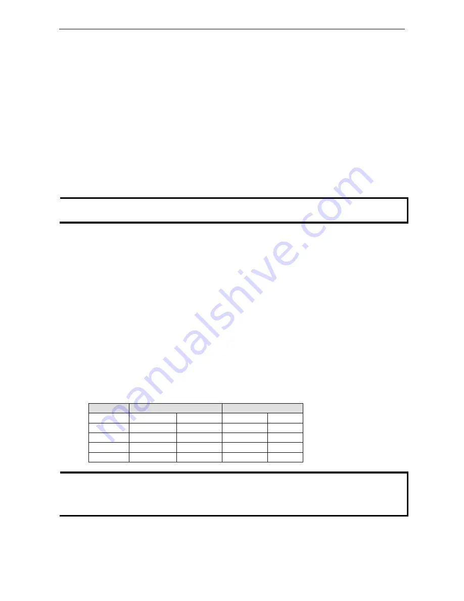
connection between the VPort D361 and the VPort encoder is ready. The PTZ port uses a 5-pin terminal block
for the RS-232/422/485 serial connection. The pin assignments are shown in the following table.
PIN
RS-422/485
RS-232
1
GND
Ground
GND
Ground
2
R-
Rx-
–
N/A
3
R+
Rx+
RxD
RxD
4
T-\D-
Tx-/Data-
–
N/A
5
T+\D+
Tx+/Data+
TxD
TxD
NOTE
The VPort D361 supports Transparent PTZ control, which means that the VPort D361 can connect directly to the
PTZ control panel or keyboard to control the remote PTZ camera connected to the VPort series video encoders.
Since the PTZ control protocol is not standardized, the PTZ control panel and keyboard must support the control
of PTZ cameras.


