11
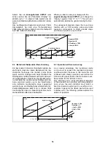
Hinweis zur Bitausblendung:
Die Verwendung dieser Funktion führt zu einer
veränderten Auswertung der Geberinformation,
und Sie müssen sich über die Auswirkung der
Ausblendung jedes einzelnen Bits in Bezug auf
Auflösung, Schrittzahl und Anzahl der registrier-
ten Umdrehungen klar sein. Das nachfolgende
Beispiel erklärt anhand eines 13-Bit-Singleturn-
Gebers die Konsequenzen der Bitausblendung:
•
Ohne Bitausblendung liefert der Geber bei
einer Drehung der Geberwelle von 0º bis
360º die Informationen 0 - 8191.
Hierzu gelten die Einstellungen „Hi_bit=13“
und „Lo_bit =01“.
Es gibt nun zwei unterschiedliche Möglichkei-
ten, nur 12 von den insgesamt 13 Bit auszuwer-
ten:
•
Wir setzen Hi_bit auf 12 und belassen
Lo_bit auf 01. Damit ist das höchste Bit
ausgeblendet. Das Resultat entspricht nun
einem Geber, der im Bereich 0º - 180º die
Informationen 0 – 4095 und im Bereich von
180º - 360º nochmals dieselben Informatio-
nen 0 – 4095 erzeugt. An der Auflösung
selbst hat sich nichts geändert.
•
oder wir belassen Hi_bit auf 13 und setzen
Lo_bit auf 02. Damit ist das kleinste Bit
ausgeblendet. Das Resultat entspricht nun
einem Geber, der im Bereich von 0º - 360º
nur einmal die Information 0 – 4095 er-
zeugt. Die Auflösung hat sich jedoch hal-
biert.
Hint for the use of the bit blanking function:
Bit blanking results in a different evaluation of the
encoder information, and you should be fully
aware of what happens with the resolution and
the number of registered turns when you use this
function.
The subsequent example uses a 13-bit single-
turn encoder to explain various result of bit blank-
ing:
•
Without blanking, a 13 bit encoder would
provide a 0 – 8192 information with a 0 - 360º
turn of the encoder shaft.
This assumes setting of “Hi_bit = 13” and
“Lo_bit = 01”.
It is easy to understand that there are two differ-
ent ways how to use only 12 of the 13 bits avail-
able:
•
When we set Hi_bit to 12 while Lo_bit re-
mains 01, we have blanked the high order
bit. The result corresponds to an encoder
providing information 0 – 4095 while we turn
from 0 - 180º, and again the same 0 – 4095
information while we turn from 180º to 360º.
The resolution remains unchanged with re-
spect to the real encoder resolution.
•
We can also leave Hi_bit to 13 and set Lo_bit
to 02 instead. This means we blank the low
order bit now. As a result, within one turn of
0 - 360º, we receive the encoder information
0 – 4095 one time only, but the resolution
has been halved.
Direction:
Dieser Parameter erlaubt die
Negierung des SSI-Einlesewertes, was
wie eine Umkehrung der Drehrichtung
des Gebers wirkt.
0
: steigende Werte bei Vorwärtsbe-
wegung
1:
steigende Werte bei Rückwärts-
Bewegung
Direction:
This register allows inver-
sion of the SSI data word, and the re-
sult is similar to a change of the direc-
tion of rotation of the encoder.
0:
increasing values with forward mo-
tion
1:
increasing values with reverse mo-
tion
Error:
Definiert die Position des Error-
Bits.
00:
kein Error-Bit vorhanden
13:
Bit 13 = Error-Bit
25:
Bit 25 = Error.Bit
usw.
Error:
Defines the location of the Er-
ror
bit
00:
no error bit available
13:
Bit 13 = Error bit
25:
Bit 25 = Error bit
etc.
Error-Polarität:
. Definiert die Polarität
des Error Bits im Fehlerfall.
0:
Bit ist
Low im Fehlerfall
1:
Bit ist
High im Fehlerfall
Error-Polarity:
defines the polarity of
the Error bit in case of error
0:
Bit is Low in case of error
1:
Bit is High in case of error
Anmerkung:
Im Fehlerfall erscheint auf der Anzeige
„Err-b“.
Mit dieser Funktion kann auch das Spannungs-
überwachungsbit (bei vielen Geberherstellern als
„PFB“ bezeichnet) ausgewertet werden.
Remark:
In case of error,
„Err-b“
appears in the display.
This function also allows to monitor the voltage
control bit (called “PFB” by some encoder manu-
facturers)


