


Canopy
T1/E1
Multiplexer
September
2004
T1/E1
Multiplexer
FPGA
Version
3.4
Page
29 of 73
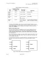
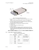
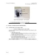
Figure 11: Front panel and front bezel removed
3. Place the Canopy T1/E1 Multiplexer behind the desired Rack Panel mounting
hole.
NOTE:
The Rack Panel will support three (3) Canopy T1/E1 Multiplexers.
4. Place the Front Panel on the front of the Rack Panel opening, positioning the
Rack Panel Spacer between the two panels.
5. Insert the front panel mounting screws through the screw holes.
6. Tighten
screws.
7. Insert the screw posts onto the DB-9 connector.
8. Tighten screw posts.
9. Mount the Canopy T1/E1 Multiplexer with the rack panel onto your rack unit.
Consult the product information supplied by the rack manufacturer for details.
NOTE:
The front panel mounting screws should be 4-40 screws, between 3/8”
and 5/8” long.
end of procedure
2.2.4
Connecting
the
Canopy
T1/E1
Multiplexer
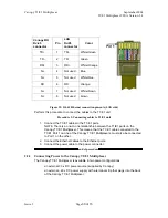
Table 12: T1/E1 port connector pin-out
Pin Designation Direction
Function
1 RD(R)
Input
Receive data (ring)
2 RD(T)
Input
Receive data (tip)
3 FGND
4
TD(R)
Output
Transmit data (ring)
5
TD(T)
Output
Transmit data (tip)
6 FGND
7, 8
FGND
Not connected
Issue
3