Issue 1.1 April 2006
Page 39
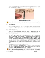
The cable should be assembled to the following instructions:
Step 1: Assemble gland on cable as shown
Step 2: Strip the outer insulation
Step 3: Arrange conductors as shown in
Figure 14 and cut to length
Step 4: Insert conductors and crimp
Figure 13: Completed ODU connector
Both ends of the ODU cable are terminated in the same way. The above procedure should be
repeated for the Canopy 150/300 PIDU end of the cable when the cable routing process is
complete.
Note: The Canopy 150/300 PIDU end of the cable does not employ a cable gland.
Summary of Contents for Canopy 150 Mbps Backhaul
Page 1: ...Canopy 150 300 Mbps Backhaul User Guide BH150 300 UG en Issue 1 1 April 2006 ...
Page 25: ...Issue 1 1 April 2006 Page 24 Figure 5 Canopy 150 300 PIDU Power Input ...
Page 97: ...Issue 1 1 April 2006 Page 96 Figure 59 Spectrum Management Help Page ...
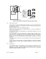
Page 162: ...Issue 1 1 April 2006 Page 161 Figure A8 Surge Arrestor ALPU ORT Connection Illustration ...


