DMR 50-5/50 Installation Guide V3.0 Pag. 2
1
Index
2
Product Presentation .................................................................................................................... 4
2.1
General Description ............................................................................................................... 4
3
Safety Information ....................................................................................................................... 5
3.1
Warnings .............................................................................................................................. 6
3.2
Cautions ............................................................................................................................... 7
3.3
Directives and Standards ........................................................................................................ 8
3.4
CE Mark Conformance ............................................................................................................ 8
3.5
Warranty Information ............................................................................................................ 8
3.6
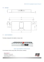
Drawings .............................................................................................................................. 9
3.7
Typical Installation ................................................................................................................. 9
3.8
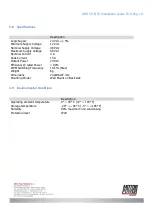
Specifications ...................................................................................................................... 10
3.9
Environmental Conditions ..................................................................................................... 10
3.10
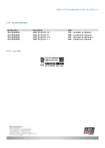
Available Models .................................................................................................................. 11
3.10.1
Type Plate .................................................................................................................... 11
4
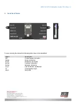
Location of Items ....................................................................................................................... 12
5
Wiring ....................................................................................................................................... 13
5.1
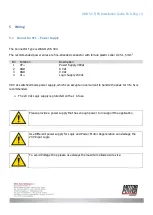
Connector XP1 – Power Supply ............................................................................................. 13
5.2
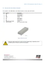
Connector M1, M2 – Motor Connector ................................................................................... 14
5.3
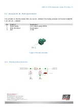
Connector P1, P2 - Photo Eye Connector ............................................................................... 15
5.3.1
Photo Eye internal connection ........................................................................................ 15
5.4
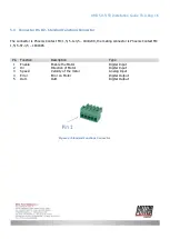
Connector D1, D2 - Standard Function Connector ................................................................... 16
5.4.1
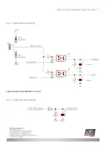
Digital Input internal wiring ............................................................................................ 17
5.4.2
Analog Input internal wiring ........................................................................................... 17
5.4.3
Digital Output Internal wiring ......................................................................................... 18
5.5
Connector N1,N2 - Network Connection ................................................................................. 19
6
Connection schematic ................................................................................................................. 20
6.1
Schematic circuit for power and logic supply ......................................................................... 21
7
Default I/O Functionality ............................................................................................................. 21
7.1
Run/Stop ............................................................................................................................ 21

