background image

9.3  Notes on Grease Replenishment/Exchange Procedures

9-9

HW0484074

HW0484074

9.3.2

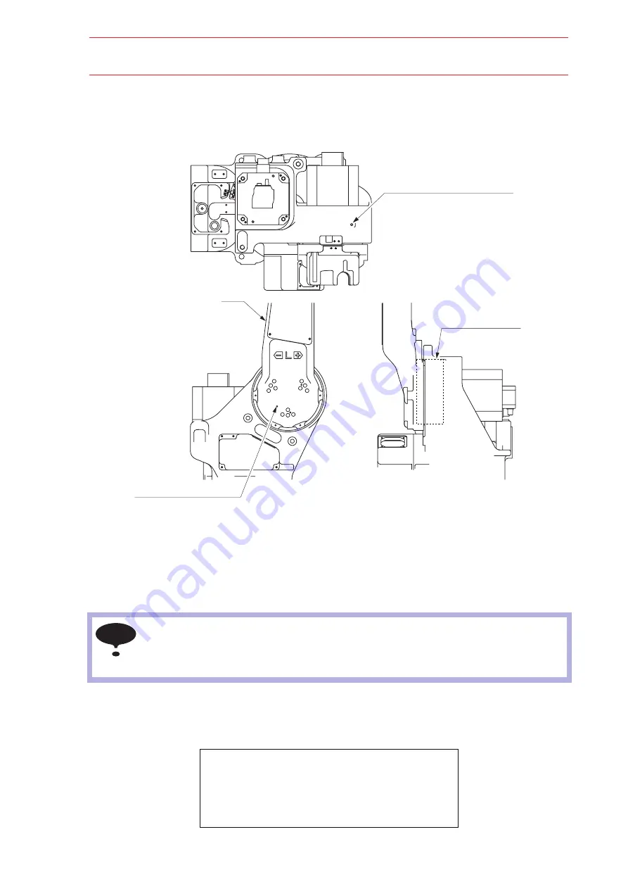
Grease Replenishment/Exchange for L-axis Speed 

Reducer

Fig. 23  L-axis Speed Reducer

T

Grease Replenishment (Refer to "Fig. 23  L-axis Speed Reducer")

1. Posture the L-arm vertical to the ground.
2. Remove the hexagon socket head plug PT1/8 from the grease exhaust port.

3. Remove the hexagon socket head cap screw M6 from the grease inlet and install the 

grease zerk A-MT6 x 1. (The grease zerk is delivered with the manipulator.)

4. Inject grease from the grease inlet using a grease gun.

• If grease is injected with the plug on, the grease will go inside the motor and may cause a 

damage.  Make sure to remove the plug before the grease injection.

• Do not install a joint, a hose, etc. to the grease exhaust port.  Failure to observe this 

instruction may result in damage to the motor due to coming off of an oil seal.

Grease type: VIGO Grease RE No. 0

Amount of grease: 150 cc

(300 cc for 1st supply)

Air supply pressure of grease pump: 0.3 MPa or less

Grease injection rate: 8 g/s or less

Grease exhaust port
(Hexagon socket head plug PT1/8)

L-arm

Grease inlet
(Hexagon socket head cap screw M6)

L-axis speed reducer

NOTE

47/59

Summary of Contents for EA1800N

Page 1: ...Liberty Lane West Carrollton Ohio 45449 USA 937 847 6200 Voice 937 847 6277 Fax 937 847 3200 24 Hour Support www motoman com info motoman com Motoman NX100 Controller EA1800N Manipulator Manual Part Number 154992 1CD Revision 0 ...

Page 2: ...rved Because we are constantly improving our products we reserve the right to change specifications without notice MOTOMAN is a registered trademark of YASKAWA Electric Manufacturing COMPLETE OUR ONLINE SURVEY Motoman is committed to total customer satisfaction Please give us your feedback on the technical manuals you received with your Motoman robotic solution To participate go to the following w...

Page 3: ...A1800N manipulator CHAPTER 4 EPH130R INSTRUCTIONS Provides detailed information for the EPH130R manipulator 1 2 Reference to Other Documentation For additional information refer to the following NX100 Controller Manual P N 149201 1 Concurrent I O Manual P N 149230 1 Operator s Manual for your application Vendor manuals for system components not manufactured by Motoman 1 3 Customer Service Informat...

Page 4: ...Manipulator Manual Chapter 1 Introduction page 2 Final Notes ...

Page 5: ...boticIndustriesAssociation 900VictorsWay P O Box3724 AnnArbor Michigan48106 TEL 734 994 6088 FAX 734 994 3338 INTERNET www roboticsonline com Ultimately the best safeguard is trained personnel The user is responsible for providing personnel who are adequately trained to operate program and maintain the robot cell The robot must not be operated by personnel who have not been trained We recommend th...

Page 6: ...e protection of personnel from the immediate and imminent hazards that if not avoided will result in immediate serious personal injury or loss of life in addition to equipment damage WARNING Information appearing in a WARNING concerns the protection of personnel and equipment from potential hazards that can result in personal injury or loss of life in addition to equipment damage CAUTION Informati...

Page 7: ... STOP mode whenever it is not in use In accordance with ANSI RIA R15 06 1999 section 4 2 5 Sources of Energy use lockout tagout procedures during equipment maintenance Refer also to Section 1910 147 29CFR Part 1910 Occupational Safety and Health Standards for General Industry OSHA 2 4 Mechanical Safety Devices The safe operation of the robot positioner auxiliary equipment and system is ultimately ...

Page 8: ...pervisors and anyone working near the robot must become familiar with the operation of this equipment Improper operation can result in personal injury and or damage to the equipment Only trained personnel familiar with the operation manuals electrical design and equipment interconnections of this robot should be permitted to program operate and maintain the system All personnel involved with the o...

Page 9: ...l modifications made to the controller will change the way the robot operates and can cause severe personal injury or death as well as damage the robot and other parts of the system Double check all modifications under every mode of robot operation to ensure that you have not created hazards or dangerous situations Check and test any new or modified program at low speed for at least one full cycle...

Page 10: ...Manipulator Manual Chapter 2 Safety page 8 Final Notes ...

Page 11: ...TCHES Upon receipt of the product and prior to initial operation read these instructions thoroughly and retain for future reference MOTOMAN INSTRUCTIONS MOTOMAN EA1800N INSTRUCTIONS NX100 INSTRUCTIONS NX100 OPERATOR S MANUAL NX100 MAINTENANCE MANUAL The NX100 operator s manuals above correspond to specific usage Be sure to use the appropriate manual 1 59 ...

Page 12: ...awings and photos in this manual are representative examples and differences may exist between them and the delivered product YASKAWA may modify this model without notice when necessary due to product improvements modifications or changes in specifications If such modification is made the manual number will also be revised If your copy of the manual is damaged or lost contact a YASKAWA rep resenta...

Page 13: ...icates a potentially hazardous situation which if not avoided could result in death or serious injury to personnel Indicates a potentially hazardous situation which if not avoided could result in minor or moderate injury to personnel and damage to equipment It may also be used to alert against unsafe practices Always be sure to follow explicitly the items listed under this heading Must never be pe...

Page 14: ...ency Stop Observe the following precautions when performing teaching operations within the P point maximum envelope of the manipulator View the manipulator from the front whenever possible Always follow the predetermined operating procedure Ensure that you have a safe place to retreat in case of emergency Improper or unintended manipulator operation may result in injury Confirm that no persons are...

Page 15: ...ary processing has been performed Check for problems in manipulator movement Check for damage to insulation and sheathing of external wires Always return the programming pendant to the hook on the NX100 cabi net after use The programming pendant can be damaged if it is left in the P point maximum envelope of manipulator on the floor or near fixtures Read and understand the Explanation of the Warni...

Page 16: ... important information is placed on the body of the manipula tor Prior to operating the manipulator confirm the contents Warning label A Warning label B Nameplate Warning label A WARNING Do not enter robot work area WARNING Moving parts may cause injury Warning Label A Warning Label B MOTOMAN TYPE PAYLOAD ORDER NO SERIAL NO MASS DATE YASKAWA ELECTRIC CORPORAION JAPAN kg kg Nameplate 6 59 ...

Page 17: ...stallation Example 3 3 3 3 Installation Method 3 4 3 3 1 S axis Operating Range 3 4 3 3 2 Fixing the Manipulator Base 3 4 3 3 3 Precautions to Prevent the Manipulator from Falling 3 4 3 4 Location 3 5 4 Wiring 4 1 Grounding 4 2 4 2 Manipulator Cable Connection 4 2 4 2 1 Connection to the Manipulator 4 3 4 2 2 Connection to the NX100 4 3 5 Basic Specifications 5 1 Basic Specifications 5 1 5 2 Part ...

Page 18: ...ocedures 9 5 9 2 1 Battery Pack Replacement 9 5 9 3 Notes on Grease Replenishment Exchange Procedures 9 7 9 3 1 Grease Replenishment Exchange for S axis Speed Reducer 9 7 T Grease Replenishment Refer to Fig 22 S axis Speed Reducer 9 7 T Grease Exchange Refer to Fig 22 S axis Speed Reducer 9 8 9 3 2 Grease Replenishment Exchange for L axis Speed Reducer 9 9 T Grease Replenishment Refer to Fig 23 L ...

Page 19: ... axis Speed Reducer 9 13 9 3 5 Grease Replenishment for B Axis Speed Reducer 9 14 9 3 6 Grease Replenishment for T axis Gear 9 15 9 3 7 Notes for Maintenance 9 17 T Wrist Axis 9 17 T Encoder Connector With CAUTION Label 9 18 10 Recommended Spare Parts 9 59 ...

Page 20: ...formation for the content of optional goods is given separately Manipulator NX100 Programming pendant Manipulator cables between the NX100 and the manipulator Confirm that the manipulator and the NX100 have the same order num ber Special care must be taken when more than one manipulator is to be installed If the numbers do not match manipulators may not perform as expected and cause injury or dama...

Page 21: ...ERT NEXT L L R LOCK INTER WEAVING START 7 R B B z T WELD START 8 FEED 9 TESTRUN SHIFT z T EX AXIS SWITCH ROBOT SWITCH SHIFT Y Y 0 ENTER CABCEK INTER REF POINT MODIFY VOLTAGE CURRENT SHORTCUT MENU THE MANIPULATOR AND THE CONTROLLER SHOULD HAVE SAME ORDER NUMBER ORDER NO Check that the manipulator and the NX100 have the same order number Label Enlarged View NX100 200V 50Hz kVA 3PHASE 220V 50 60Hz NJ...

Page 22: ...or damage Avoid excessive vibration or shock during transport The system consists of precision components Failure to observe this caution may adversely affect performance Check that the eyebolts are securely fastened The mass of the manipulator is approximately 385 kg including the shipping bolts and brackets Use a wire rope strong enough to withstand the mass The attached eyebolts are designed to...

Page 23: ...orting Method 2 2 HW0484074 HW0484074 Fig 2 Transporting Position E View E Eyebolt M16 2 eyebolts Fixed to the manipulator before shipment Eyebolt M16 2 eyebolts Fixed to the manipulator before shipment A B 13 59 ...

Page 24: ...ng bolts and brackets as shown in Fig 3 Using a Forklift Use a pallet strong enough to support the manipulator Insert forklift claws under the pallet and lift it together with the manipulator and slowly transport the manipulator with due caution to avoid overturn or slippage Fig 3 Using a Forklift Bolt M16 4 bolts Pallet Forklift claw entries 14 59 ...

Page 25: ...pping bracket A is painted yellow and fixed with two hexagon socket head cap screws M6 A rubber cushion is wedged at point B Before turning ON the power check to be sure that the shipping bolts bracket and rubber cushion have been removed They must be stored for future use in the event that the manipulator must be moved again for relocation B A Shipping Bracket A Eyebolt M16 2 eyebolts Fixed to th...

Page 26: ...ause injury or damage When mounting the manipulator on the ceiling or wall the base section must have sufficient strength and rigidity to support the mass of the manipulator Also it is necessary to consider countermeasures to pre vent the manipulator from falling Failure to observe these warning may result in injury or damage Do not install or operate the manipulator that is damaged or lacks parts...

Page 27: ...anipulator should be firmly mounted on a base or foundation strong enough to support the manipulator and withstand repulsion forces during acceleration and deceleration Refer to Table 1 Maximum Repulsion Force of the Manipulator at Emergency Stop and Table 2 Endurance Torque in Operation to construct a solid foundation with the appropriate thickness to withstand maximum repulsion forces of the man...

Page 28: ...recom mended length 60 mm using the mounting holes on the manipulator base Fig 4 Manipulator Installation Example Tighten the anchor bolts and the hexagon head screws securely so that they will not work loose during operation For details refer to Fig 4 Manipulator Installation Example NOTE 300 380 335 195 0 1 380 335 50 120 50 120 344 170 0 1 130 0 1 130 0 1 A 40 or more 25 Screw M16 4 screws Spri...

Page 29: ...ange of wall mounted type manipulator shall be 30 Changed prior to shipment 3 3 2 Fixing the Manipulator Base The wall mounted type manipulator shall be securely fixed with four hexagon socket head cap screws M16 tensile strength 1200 N mm2 or more Use a torque of 206 NNm in tightening the screws 3 3 3 Precautions to Prevent the Manipulator from Falling To ensure safety be sure to take preventive ...

Page 30: ...ditions 0 to 45 C ambient temperature 20 to 80 RH non condensing Free from dust soot or water Free from corrosive gases or liquid or explosive gases Free from excessive impact or vibration vibration acceleration 4 9 m s2 0 5 G or less Free from large electrical noise plasma The flatness for installation is 0 5 mm or less 20 59 ...

Page 31: ...ock Before wiring make sure to turn OFF the primary power supply and put up a warning sign ex DO NOT TURN THE POWER ON Failure to observe this warning may result in fire or electric shock Wiring must be performed by authorized or certified personnel Failure to observe this caution may result in fire or electric shock WARNING CAUTION 21 59 ...

Page 32: ...r cables 2BC and 3BC Refer to Fig 6 Manipulator Cables For each connection refer to Fig 7 a Manipulator Cable Connection To the Manipulator and Fig 7 b Manipulator Cable Connection To the NX100 Never use this line sharing with other ground lines or grounding electrodes for other elec tric power motor power welding devices etc Where metal ducts metallic conduits or distributing racks are used for c...

Page 33: ...r base of the manipulator and set the lever low until it clicks 4 2 2 Connection to the NX100 Before connecting the manipulator cables to the NX100 verify the connector numbers both the cables and the connectors on the NX100 are marked with X11 X21 and X22 Connect the cables in the order of X22 X21 X11 referring to Fig 7 b Manipulator Cable Connection To the NX100 When connecting insert each cable...

Page 34: ...tor Cable Connection 4 4 HW0484074 HW0484074 Fig 7 a Manipulator Cable Connection To the Manipulator Fig 7 b Manipulator Cable Connection To the NX100 Connector Details Manipulator AIR 2BC 1BC 3BC X22 X21 X11 24 59 ...

Page 35: ...er arm 210 175 R axis wrist roll 175 B axis wrist pitch yaw 180 45 T axis wrist twist 200 Maximum Speed S axis 3 40 rad s 195 s L axis 2 96 rad s 170 s U axis 3 05 rad s 175 s R axis 5 93 rad s 340 s B axis 5 93 rad s 340 s T axis 9 08 rad s 520 s Allowable Moment 3 R axis 38 6 NRm 3 9 kgfRm B axis 38 6 NRm 3 9 kgfRm T axis 7 35 NRm 0 75 kgfRm Allowable Inertia GD2 4 3 R axis 1 04 kgRm2 B axis 1 0...

Page 36: ...xes 5 3 Manipulator Base Dimensions Fig 9 Manipulator Base Dimensions T B T B U U L R R L S S Upper arm U arm Wrist Lower arm L arm Rotary head S head Manipulator base 0 015 0 12 dia hole 2 holes 18 dia hole 4 holes 300 25 344 195 0 1 195 0 1 170 0 1 50 120 380 335 130 0 1 130 0 1 50 120 380 335 View A A Units mm 26 59 ...

Page 37: ...aximum Envelope Fig 10 Dimensions and P Point Maximum Envelope P point P point maximum envelope 30 30 277 185 1 5 5 1 0 0 155 106 R509 110 180 180 175 3243 2212 914 322 471 0 1031 429 202 509 0 1507 1242 376 1807 81 R1807 68 122 79 1535 220 760 555 45 870 150 285 219 A 30 110 View A Units mm 27 59 ...

Page 38: ...ange of the S axis can be altered according to the operating conditions as shown in Table 4 S axis Operating Range If alteration is necessary contact your Yaskawa representative in advance Table 4 S axis Operating Range Item Specifications S axis Operating Range 180 standard 150 120 90 60 30 28 59 ...

Page 39: ... 5 Allowable Total Moment of Wrist 1 Gravitational unit When the volume load is small refer to the moment arm rating shown in Fig 11 Moment Arm Rating The allowable inertia is calculated when the moment is at the maximum Contact your Yaskawa representative when only load inertia or load moment is small and inertia is large Also when the load is combined as a force but a mass contact your Yaskawa r...

Page 40: ...e the fitting Fitting depth of inside and outside fittings shall be 6 mm or less Fig 12 Wrist Flange Wash off anti corrosive paint yellow color on the wrist flange surface with thinner or light oil before mounting the tools 2 30 P C D 56 100 dia 45 dia 0 025 0 Range of 45 dia 0 025 0 0 012 0 6 dia hole depth 6 Tapped hole M4 pitch 0 7 depth 8 6 holes Units mm 6 NOTE 30 59 ...

Page 41: ... Mass The allowable mass loaded on the U Axis is a maximum of 24 kg including the mass on the wrist For instance when the mass installed in the wrist point is 15 kg the allowable mass on the upper arm would be 9 kg or less The allowable mass on the S head the rotary head is a maximum of 20 kg Mount the peripheral equipment on the S head so that the moment of inertia GD2 4 from the S axis rotation ...

Page 42: ...4 100 190 75 55 40 Mount the peripheral equipment within this range A 70 AIR 2BC 1BC 3BC Tapped hole M8 pitch 1 25 depth 18 2 holes Tapped hole M6 pitch 1 0 depth 14 2 holes View A Gravity point of the peripheral equipment on the U arm is to be set within this range Tapped hole M10 pitch 1 5 depth 20 4 holes Units mm 32 59 ...

Page 43: ...he figure and the conditions below The Allowable Current for Internal User I O Wiring Harness 3 A or less for each cable The total current value for pins 1 to 16 shall be 40 A or less The Maximum Pressure for the Air Line 490 kPa 5 kgf cm2 or less Inside diameter 6 5 mm Fig 14 Internal User I O Wiring Harness and Air Line Air inlet Tapped hole PT3 8 with pipe plug AIR 2BC 1BC 3BC A AIR 2BC 1BC 3BC...

Page 44: ... 7 11 5 16 15 4 9 13 2 3 1 25 mm2 1 25 mm2 1 25 mm2 1 25 mm2 1 25 mm2 Open Open Internal user I O wiring harness 0 2 mm 2 x 8 wires 1 25 mm 2 x 6 wires 3 4 5 1 2 9 10 11 16 15 13 14 12 6 7 8 Pins Used 3 4 5 1 2 9 10 11 16 15 13 14 12 6 7 8 Pins Used Connector for Internal User I O Wiring Harness Connector Base Connector for Internal User I O Wiring Harness U arm Power for shock sensor 24 V 1 A Sig...

Page 45: ... optional For each location refer to Fig 16 Location of Limit Switch A manipulator type with the S or L axis overrun limit switch or the LU axis interference limit switch is YR EA1800N A01 Fig 16 Location of Limit Switch L axis overrun limit switch optional S axis overrun limit switch optional LU axis interference limit switch optional 35 59 ...

Page 46: ...onnectors refer to Fig 17 Location of Connectors and Table 6 Con nector Types Fig 17 Location of Connectors Table 6 Connector Types Name Type of Connector Connector for internal user I O wiring harness on connector base JL05 2A20 29PC JL05 6A20 29S Optional Connector for internal user I O wiring harness on U arm JL05 2A20 29SC JL05 6A20 29P Optional AIR 2BC 1BC 3BC 3BC connector for internal user ...

Page 47: ...11 10 9 7 1 4 2 3 6 2 3 1 5 4 BAT 0BT 0BT 0BT BAT 7 1 8 7 4 5 6 3 2 0BT BAT BAT 6 R K K R R K K R P P P P 0V 0V 24V 24V 2 3 4 1 8 0BAT22 BAT22 0BAT21 BAT21 0BAT12 BAT11 BAT12 0BAT11 CN1 2 CN1 1 CN1 9 CN1 5 CN1 10 CN1 4 CN1 7 CN1 6 CN1 3 P P P P SPG 2 SPG 2 FG1 1BC 10Px4 SPG 1 SPG 1 0V 0V 24V 24V CN2 2 CN1 8 CN2 1 CN2 7 CN2 6 CN2 3 P P CN3 3 CN3 2 CN3 1 CN2 8 CN3 6 CN3 8 CN3 7 P P CN4 6 CN4 1 CN4 3...

Page 48: ...4 4BC 15 4BC 12 4BC 11 4BC 7 4BC 8 4BC 10 4BC 9 MU1 MU1 E MV1 MV1 MW1 MV1 MU1 ME1 ME1 ME1 MW1 MU3 MU3 MV3 MW1 CN1 5 CN2 1 CN1 6 CN1 3 CN1 4 CN1 1 CN1 2 CN3 1 CN3 3 CN3 2 CN2 4 CN2 6 CN2 5 CN2 3 CN2 2 2BC 6X6 MW3 MW3 MV3 ME3 MU4 MW4 MV4 BA1 ME4 BB3 BB2 BA3 BA2 BB1 ME3 CN3 5 CN3 6 CN3 4 CN4 4 CN4 2 CN4 3 CN4 1 CN5 1 CN5 6 CN5 5 CN5 4 CN5 2 CN5 3 CN4 6 CN4 5 BB5 BA4 BA5 BB4 BB6 BA6 MU2 E MV2 MV2 MV2 ...

Page 49: ...ly and put up a warning sign ex DO NOT TURN THE POWER ON Failure to observe this warning may result in electric shock or injury Maintenance and inspection must be performed by specified personnel Failure to observe this caution may result in electric shock or injury For disassembly or repair contact your Yaskawa representative When performing maintenance and inspection make sure to connect the bat...

Page 50: ...e if necessary 7 Connector base Manual Check for loose connectors 8 BT axis timing belts Manual Check for belt tension and wear 9 Wire harness in manipula tor for SLU axes and for RBT axes Visual multimeter Check for conduc tion between the main connector of connector base and intermediate con nector by manually shaking the wire Check for wear of protective spring 1 Replace 2 10 Wire harness in ma...

Page 51: ... 7 Inspection Items 14 U axis speed reducer Grease gun Check for malfunc tion Replace if nec essary Supply grease 6000H cycle 3 Exchange grease 12000H cycle 3 See section 9 3 3 15 R axis speed reducer Grease gun Check for malfunc tion Replace if necessary Supply grease 6000H cycle 3 See section 9 3 4 16 B axis speed reducer Grease gun Check for malfunc tion Replace if necessary Supply grease 6000H...

Page 52: ...1 Inspection Schedule 9 4 HW0484074 HW0484074 13 4 5 8 8 15 16 11 12 14 17 4 4 The manipulator is in the home position Fig 19 Inspection Parts and Inspection Numbers Manipulator in the Home Position 42 59 ...

Page 53: ...ocedure Fig 20 Battery Pack Location Fig 21 Battery Pack Connection 1 Turn OFF the NX100 main power supply 2 Remove the cover plate fixing screws from the connector base and pull out the battery pack to replace with a new one Cover plate fixing screw Cover plate Connector base Battery pack Support AIR 2BC 1BC 3BC Connector Battery pack before replacement See the step 5 New battery pack Circuit boa...

Page 54: ...board 5 Remove the old battery pack from the circuit board 6 Mount the new battery pack to the battery holder 7 Reinstall the cover plate and fix it with the plate fastening screws Make sure to connect the new battery pack before removing the old one so that the encoder absolute data will not disappear Do not allow plate to pinch the cables when reinstalling the plate NOTE NOTE 44 59 ...

Page 55: ...sure to remove the plug Do not install a joint a hose etc to the grease exhaust port Failure to observe this instruction may result in damage to the motor due to coming off of an oil seal Make sure to use a grease pump to inject grease Set air supply pressure to the grease pump at 0 3 MPa or less and the grease injection rate at 8 g s or less Make sure to fill the hose on the grease inlet with gre...

Page 56: ...g a grease gun 4 The grease exchange is completed when new grease appears in the exhaust port The new grease can be distinguished from the old grease by color 5 Move the S axis for a few minutes to discharge excess grease 6 Wipe the discharged grease with a cloth and remove the grease zerk from the grease inlet Reinstall the plug PT1 8 on the grease inlet and the grease exhaust port Apply Three Bo...

Page 57: ... manipulator 4 Inject grease from the grease inlet using a grease gun If grease is injected with the plug on the grease will go inside the motor and may cause a damage Make sure to remove the plug before the grease injection Do not install a joint a hose etc to the grease exhaust port Failure to observe this instruction may result in damage to the motor due to coming off of an oil seal Grease type...

Page 58: ...nlet using a grease gun 5 The grease exchange is completed when new grease appears in the exhaust port The new grease can be distinguished from the old grease by color 6 Move the L axis for a few minutes to discharge excess grease 7 Wipe the discharged grease with a cloth and reinstall the plug PT1 8 on the grease exhaust port Apply Three Bond 1206C to the thread part of the plug and tighten the p...

Page 59: ...and tighten the screw with a tightening torque of 10 NNm 1 0 kgfNm 7 Remove the grease zerk from the grease inlet and reinstall the plug PT1 8 Apply Three Bond 1206C to the thread part of the plug and tighten the plug with a tightening torque of 4 9 NNm 0 5 kgfNm T Grease Exchange Refer to Fig 24 U axis Speed Reducer 1 Posture the U arm horizontal to the ground as shown in Fig 24 U axis Speed Redu...

Page 60: ... screw M6 on the grease exhaust port Apply Three Bond 1206C to the thread part of the screw and tighten the screw with a tightening torque of 10 NNm 1 0 kgfNm 8 Remove the grease zerk from the grease inlet and reinstall the plug PT1 8 Apply Three Bond 1206C to the thread part of the plug and tighten the plug with a tightening torque of 4 9 NNm 0 5 kgfNm If grease is injected with the screw on the ...

Page 61: ...rk A MT6 x 1 from the grease inlet and reinstall the screw M6 Apply Three Bond 1206C to the thread part of the screw and tighten the screw with a tightening torque of 6 NNm 0 6 kgfNm 5 Reinstall the plug 1 8 on the exhaust port Apply Three Bond 1206C to the thread part of the plug and tighten the plug with a tightening torque of 4 9 NNm 0 5 kgfNm Grease type Harmonic grease 4B No 2 Amount of greas...

Page 62: ...fer to Fig 26 B Axis Speed Reducer 4 Remove the grease zerk A MT6 x 1 from the grease inlet and reinstall the screw M6 Apply Three Bond 1206C to the thread part of the screw and tighten the screw with a tightening torque of 6 NNm 0 6 kgfNm 5 Reinstall the plug LPM5 on the exhaust port 6 Reinstall the cover Grease type Harmonic grease SK 1A Amount of grease 7 cc 14 cc for the 1st supply The exhaust...

Page 63: ...rease inlet 1 and reinstall the screw M6 Apply Three Bond 1206C to the thread part of the screw and tighten the screw with a tightening torque of 6 NNm 0 6 kgfNm 5 Remove the hexagon socket head cap screw M6 from the grease inlet 2 and install the grease zerk A MT6 x 1 The grease zerk is delivered with the manipulator Grease type Alvania EP Grease 2 Amount of grease 5 cc The exhaust port is used o...

Page 64: ...screw and tighten the screw with a tightening torque of 6 NNm 0 6 kgfNm 8 Reinstall the hexagon socket set screw on the exhaust port Apply Three Bond 1206C to the thread part of the set screw and tighten the set screw with a tightening torque of 2 9 NNm 0 29 kgfNm Grease type Alvania EP Grease 2 Amount of grease 5 cc The exhaust port is used only for air flow the grease is not exhausted from the e...

Page 65: ...st axis To prevent fumes from penetrating into the wrist unit the cover jointing faces are sealed with sealing bond If the wrist cover is removed for some reason make sure to reapply the sealing bond Three Bond 1206C refer to Table 9 Spare Parts for the MOTOMAN EA1800N A00 A01 when reassembling the cover Fig 28 Sealed Part of Wrist Unit Cover Cover jointing face Cover Cover jointing face 55 59 ...

Page 66: ...ttery backup connector b a a b 0BT BAT BAT 0BT HW9470932 A battery pack Motor Motor power connector Encoder connector OBT BAT OBT4 BAT4 OBT BAT OBT4 BAT4 a b a b a b a b Connected Battery Pack a Crimped contact pin socket b Crimped contact pin pin CAUTION label Enlarged View CAUTION Connect battery to encoder to save the data before removing conector Encoder Motor cable etc Connect Battery pack Po...

Page 67: ...presentative Table 9 Spare Parts for the MOTOMAN EA1800N A00 A01 Rank Parts No Name Type Manufacturer Qty Qty per Unit Remarks A 1 Grease VIGO Grease RE No 0 Yaskawa Electric Corporation 16 kg A 2 Grease Harmonic Grease 4B No 2 Harmonic Drive Systems Inc 2 5 kg A 3 Grease Grease SK 1A Harmonic Drive Systems Inc 2 5 kg A 4 Grease Alvania EP Grease 2 Showa Shell Sekiyu K K 16 kg A 5 Liquid Gasket Th...

Page 68: ...19 T axis Gear Input HW0309955 1 Yaskawa Electric Corporation 1 1 B 20 T axis Gear Unit HW0372475 A Yaskawa Electric Corporation 1 1 B 21 Wire Harness in Manipulator HW0172980 A Yaskawa Electric Corporation 1 1 B 22 Wire Harness in Manipulator for B and T axes HW0272306 A Yaskawa Electric Corporation 1 1 C 23 AC Servomotor for S and L axes HW0385669 A SGMRS 20A2A YR2 Yaskawa Electric Corporation 1...

Page 69: ...1 1061 1020 1046 1059 1025 1026 1064 1022 1023 1024 1016 1014 1017 1028 1029 1030 1044 1045 1041 1078 1053 1054 1043 1052 1055 1056 1015 1013 1019 1027 1011 1042 1010 1009 1039 1037 1038 1040 1071 1069 1068 1070 1051 1058 1057 1063 1062 1065 1066 1004 1005 1033 1034 1035 1036 1006 1007 1012 1012 1067 1075 1072 1074 1073 1018 1076 58A 59 ...

Page 70: ... HW9405846 1 Housing 1 1035 M8X70 Socket screw 1 1036 2H 8 Spring washer 1 1037 MTK 50 Zipper tube 2 1038 T50R Insulok 1 1039 M5X6 Socket screw 4 1040 2H 5 Spring washer 4 1041 FCD39 Saddle 1 1042 HW0411372 1 Support 1 1043 HW0409436 1 Support 1 1044 M5X10 GT SA bolt 2 1045 M5 Washer 2 1046 AE3400A0 Oil seal 1 1047 6813ZZ Bearing 1 1048 RTW 85 Retaining ring 1 1049 STW 80 Retaining ring 1 1050 681...

Page 71: ...0484074 11 2 L Axis Unit 2016 2026 2029 2012 2004 2009 2007 2008 2006 1060 2037 2005 2036 2038 2040 2039 2033 2034 2021 2020 2019 2035 2013 2017 2002 2001 2018 2028 2030 2027 2032 2031 2025 2023 2022 2024 2014 2015 2010 2003 2011 58C 59 ...

Page 72: ... SGMRS 20A2A YR21 Motor 1 2017 M12X45 Socket screw 4 2018 2H 12 Spring washer 4 2019 HW0309832 1 Cover 1 2020 M6X10 APS bolt 4 2021 HW0101620 1 L arm 1 2022 M12X60 Socket screw 12 2023 2H 12 Spring washer 12 2024 M8X105 Socket screw 1 2025 2H 8 Spring washer 1 2026 HW0309830 1 Gear 1 2027 M10X40 Socket screw 12 2028 2H 10 Spring washer 12 2029 HW9381641 D Speed reducer 1 2030 M6X10 Socket screw 1 ...

Page 73: ...3034 3035 3024 3032 3048 3041 3042 3015 3033 3016 3004 3008 3009 3007 3006 3047 3040 3038 3029 3030 3025 3026 3020 3021 3022 3023 3046 3019 3012 3013 3005 3049 3050 3043 44 3039 3017 3018 3027 2021 3045 3043 44 3001 02 3045 3014 3031 3003 3037 3036 3011 3010 58E 59 ...

Page 74: ... 3023 GT SH 12 Spring washer 3 3024 HW0309857 1 Input gear 1 3025 M6X65 Socket screw 1 3026 2H 6 Spring washer 1 3027 M8X30 GT SA bolt 12 3028 HW0385640 A Speed reducer 1 3029 M8X40 Socket screw 16 3030 2H 8 Spring washer 16 3031 PT1 8 Plug 1 3032 ARP568 258 O ring 1 3033 M8X30 DACROTIZED coating Socket screw 4 3034 2H 8 DACROTIZED coating Spring washer 4 3035 SGMRS 12A2B YR1 Motor 1 3036 M4X12 GT...

Page 75: ...003 4002 4009 4008 4016 4015 4023 4027 4040 4045 4020 4030 4032 4012 4041 4042 4044 4047 4031 4024 4022 4028 4052 4050 4026 4021 4038 4048 3048 4051 4049 4025 4043 4039 4029 5021 4046 4033 4007 4004 4034 4035 4036 4010 4011 4005 4006 4017 4018 4019 4037 4013 4014 58G 59 ...

Page 76: ...23 6908LLU Bearing 1 4024 STW 40 Retaining ring 1 4025 HW0372474 A R axis gear unit assy 1 4026 EZ5036A0 Plug 1 4027 6905LLU Bearing 1 4028 STW 25 Retaining ring 1 4029 HW0309856 1 Flange 1 4030 HW0304451 1 Shaft 1 4031 AE0981 H00X7 Oil seal 1 4032 HW0409458 1 Fly wheel 1 4033 M4X50 Socket screw 1 4034 2H 4 Spring washer 1 4035 HW0409459 1 Washer 1 4036 HW0309849 1 M base 1 4037 HW0381463 B Speed ...

Page 77: ... 5085 5027 5028 5038 5015 5011 5036 5019 5020 5026 5032 5092 5093 5065 5065 5069 5067 5068 5077 5037 5073 5078 5023 5024 5014 5023 5024 5005 5006 5042 5043 5075 5076 5083 5057 5095 5082 5061 5034 5060 5074 5084 5079 5081 5047 5055 5055 5056 5062 5059 5046 5001 5080 5053 5017 5091 5094 5086 5033 5002 5003 5004 5063 5049 5050 5048 5054 5045 5096 5018 5058 5051 5087 5088 5090 5089 5052 58I 59 ...

Page 78: ...W0409525 A Pulley 1 5045 6804DBLU Bearing 1 5046 HW0409520 1 B nut 1 5047 HW0309956 1 Shaft 1 5048 M6X6 H set screw 1 5049 HW0404365 1 Cover 1 5050 HW0404366 1 Packing 1 5051 HW0309955 1 Gear 1 5052 M5X12 APS bolt 2 5053 M8X25 Socket screw 1 5054 2H 8 Spring washer 1 5055 WR 17 Stopper 2 5056 IRTW 30 Stopper 1 5057 NA4903 Bearing 1 5058 M4X4 H set screw 2 5059 HW0409533 1 Coller 1 5060 HW0409522 1...

Page 79: ...IC KOREA CORPORATION 1F Samyang Bldg 89 1 Shinchun dong Donk Ku Daegu Korea Phone 82 53 382 7844 Fax 82 53 382 7845 YASKAWA ELECTRIC SINGAPORE PTE LTD 151 Lorong Chuan 04 01 New Tech Park Singapore 556741 Phone 65 6282 3003 Fax 65 6289 3003 YASKAWA ELECTRIC MALAYSIA SDN BHD Unit 47 1 and 2 Jalan PJU 5 9 Dataran Sunway Kota Damansara 47810 Petailng Jaya Selangor Malaysia Phone 60 3614 08919 Fax 60 ...

Reviews: