MORTEX
PRODUCTS
INC
501
TERMINAL
RD
FORT
WORTH,
TX
76106
Page
9
properly. To properly design the duct work for the building, refer to
the ASHRAE Fundamentals Handbook, Chapter on Duct Design or
a company that specializes in Manufactured (Mobile) Home,
Modular Home and HUD Home duct designs.
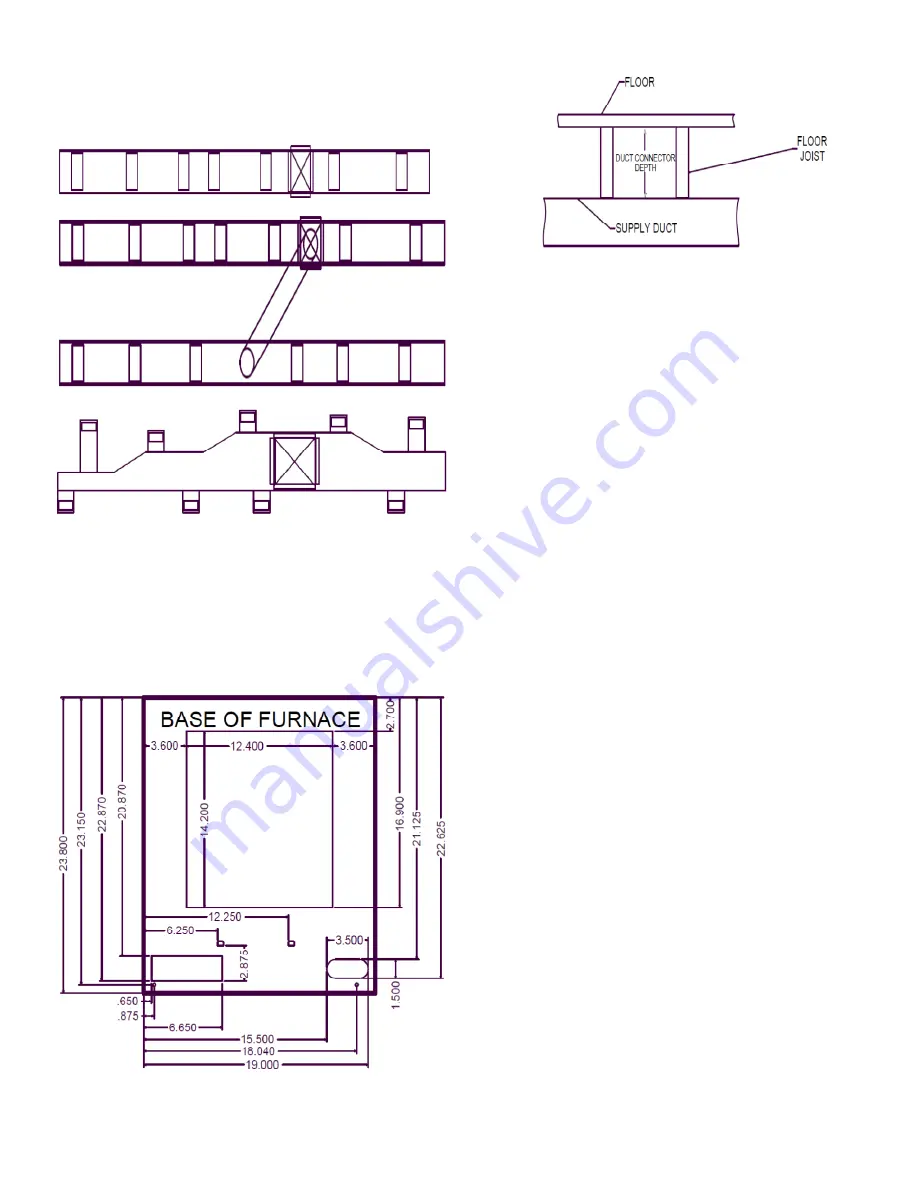
Figure 4: Air Distribution System – Single Trunk Duct
Figure 5: Air Distribution System – Double Trunk Duct
Figure 6: Air Distribution System – Graduated Trunk Duct
Important:
If the supply air duct is being connected to the
appliance without the use of an accessory duct connector, then a
transition duct must be installed with flanges or tabs that are
securely attached and sealed to the supply air duct and the base of
the appliance. The transition duct must have insulation between the
duct and any combustible material. The transition duct must be the
same dimensional size as the supply air opening in the base of the
appliance.
Figure 7: Furnace Base Openings for Fuel, Electrical and A/C
Line Penetrations
Figure 8: Duct Connector Depth
Alcove Installation
This furnace is approved for use in an alcove with both the heating
only (without an air conditioning coil) and the A/C ready models. A
minimum of 24 inches (61 cm) front clearance to a face wall or
partition is needed for service access and return air clearances.
Prior to installing the furnace make sure the holes are cut into the
floor for the refrigerant tubing, the electrical wiring is in place, the
thermostat wiring and the condenser control wiring is in place.
Install the furnace as follows:
1.
Before installing the furnace, be sure you have enough
clearance to install the furnace and clearance for the return air.
Refer to Table 1 CLEARANCES.
2.
Remove the top shipping cover and corner posts.
3.
Remove the upper access panel (door).
4.
Remove the lower access panel (door).
5.
Set the furnace in place on the duct connector. Make sure the
supply air opening lines up with the opening in the duct
connector.
6.
Slide the furnace on to the floor base. Push the furnace back
until the furnace casing is against the rear flange.
7.
Secure the furnace to the floor by drilling two holes through
the furnace base and the floor base at the right and left front
inside corners of the cabinet. Use two screws to secure the
furnace to the floor.
8.
When any air leaks have been sealed reinstall the coil cabinet
panels.
9.
Remove the roof jack assembly and replace with a new roof
jack. Be sure to follow the roof jack installation instructions
exactly.
10.
Connect the gas lines, the line voltage and low voltage wiring.
11.
Remove the coil cabinet panels and seal around the duct
connector and the furnace base to prevent air leakage.
12.
Install the cooling coil into the coil compartment (for A/C
ready models only). Replace the panels when the coil
installation is complete.
13.
Check for gas leaks. If no leaks are found then turn on the gas
to the appliance.
14.
Follow the procedure to “START THE APPLIANCE” located
in the Users Information Manual.
15.
Verify the furnace is operating properly and set the thermostat
to the desired temperature.
16.
Place the upper access panel on the furnace.
Important:
Fabricate and install an inspection door in the plenum
base below the appliance to allow an annual inspection of the heat
exchangers. The inspection door can be fabricated by the following
method.


