MN00178
1359
ACCESSORIES
Included accessories:
•
10' indoor test cable included with product, terminating with RJ45 connectors for Camera 1 & Camera 2, #6 spade lugs for GeminEye power, Illuminator
power, chassis ground.
•
Connector for user installation QuickSet part number QS50495 (generic MS3116F16-26SW). Note that customer should supply an appropriate connector
back shell for outdoor installation to provide weather sealing appropriate to the installation.
Available accessories:
•
7-17564 Kit - Curved Wall Mount Bracket
•
7-17565 Kit - Adapter w/Chain-Strap for Pole Mount, use with 7-1756
•
7-17566 Corner Mount for use with 7-17564
•
7-17567 Pedestal Mount for mounting on Horizontal surface
SECTION
II
INSTALLATION
General:
To achieve optimum results from this unit, proper installation procedures should be followed, primarily: location, mounting, & setting soft tilt limit stops. These items are
reviewed in the following sections.
Unpack and Inspect:
Carefully remove the unit from the carton and examine for signs of physical damage, particularly dented or broken parts. If any are observed, notify the freight carrier im-
mediately for claim handling. Retain all packing material until claim is settled.
Check the box contents for (1) Integrated Camera System, (1) mating connector, (1) test cable, (1) basic test software/manuals CD00556, and (1) system schematic. If any
of the above components are missing, please contact Moog immediately, and please have your sales order number available. Claims for missing components must be filed
within a reasonable time period from receipt. Retain packing box if future shipping or storage is expected.
Installation:
GENERAL:
To achieve optimum and safe results from this unit, proper installation procedures should be followed as described in section "B"; primarily these have to do with the Pan
& Tilt location and settings of the limit stops. These items are reviewed in the following paragraphs.
INSTALLATION PROCEDURES - MECHANICAL:
Site Location
Select a mounting location that will provide the desired maximum movement angles without allowing the pan and tilt or camera enclosure to come in contact with, or strike,
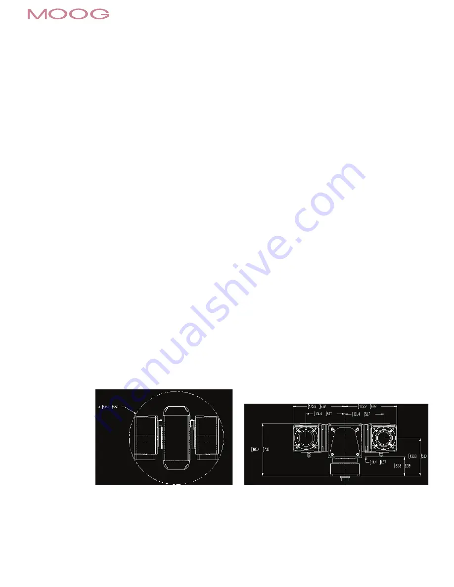
any objects in their sweep paths. Adjustable soft limits should be set to limit the degree of travel in tilt, (soft limits are set in software). Refer to the drawings below to see
the dimensions of the EXO product. Dimensions shown in brackets are metric [millimeters] while other dimensions are in inches.
Figure 1:
Standard EXO Visible /
Thermal camera version.


