Operation
XG0228 - 021419
Section 10: Cleaning and Maintenance
General
ȏ +DYHWKHȴUHSODFHDQGLQVWDOODWLRQLQVSHFWHG\HDUO\7KHLQVSHFWLRQ
must include, but is not limited to, the following:
ȏ
A visual check of the entire vent system and termination, where
accessible.
ȏ $Q LQVSHFWLRQ RI WKH H[SORVLRQ UHOLHI ȵDSSHUV DQG WKH GRRU
gaskets to ensure a proper seal.
ȏ
An inspection of the burner, vent run, and primary air openings.
ȏ $QLQVSHFWLRQRIWKHJDVYDOYHJDVFRPSRQHQWVDQGSLORWȵDPH
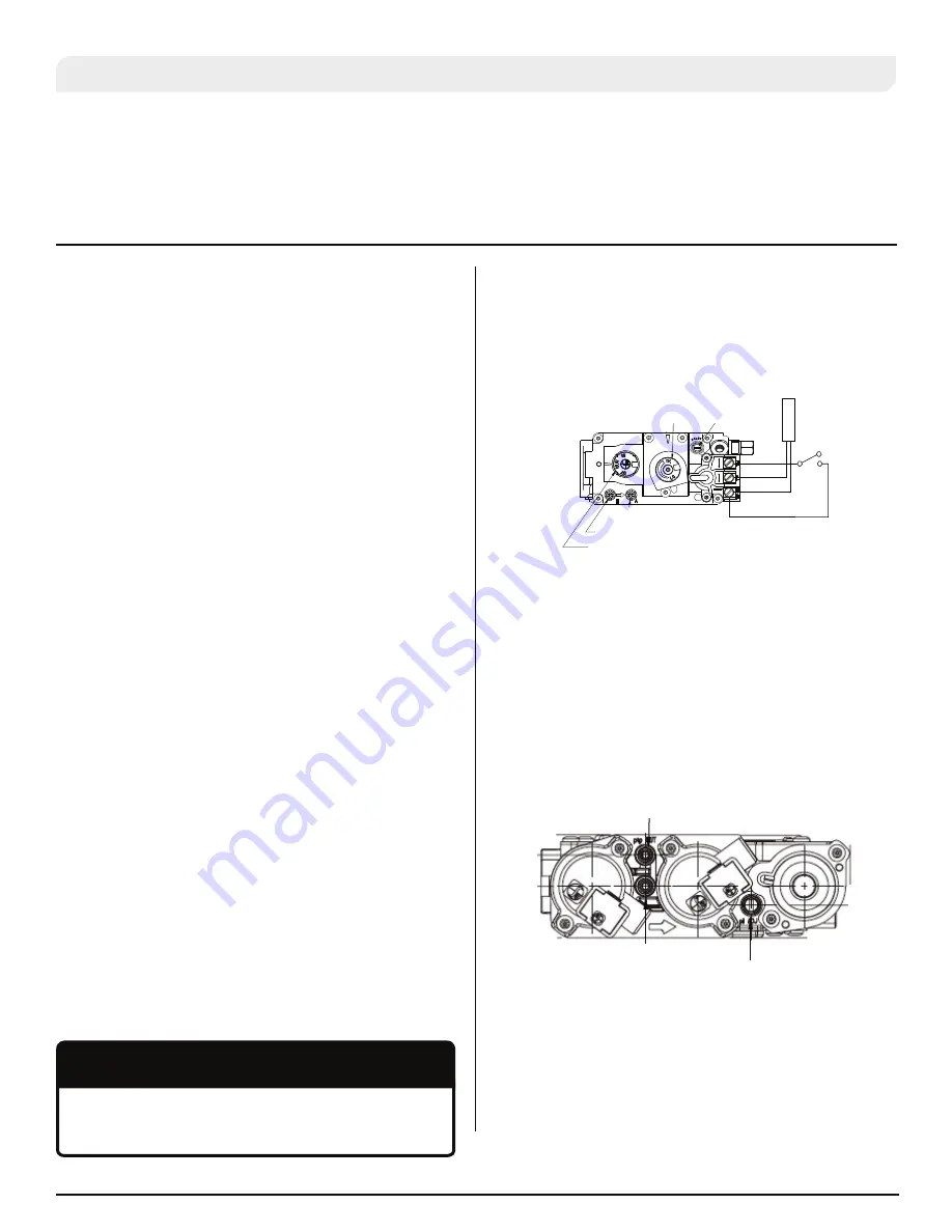
)RU\RXUFRQYHQLHQFHDPDQLIROGSUHVVXUHWDSLVVXSSOLHG
on the gas valve for a test gauge connection.
ȏ
Inspection of all optional equipment; fans, thermostats, remote
control lights, etc.
ȏ
For Natural Gas this appliance requires a minimum inlet pressure
of 5.5" W.C. and a manifold pressure of 3.5" W.C.
ȏ
For Propane Gas this appliance requires a minimum inlet pressure
of 11" W.C. and a manifold pressure of 10" W.C.
ȏ $OZD\VNHHSWKHȴUHSODFHDUHDFOHDUDQGIUHHRIFRPEXVWLEOHPDWHULDOV
DVZHOODVJDVROLQHDQGRWKHUȵDPPDEOHYDSRUVDQGOLTXLGV
ȏ
Do not use this appliance if any part has been under water.
ΖPPHGLDWHO\FDOODTXDOLȴHGVHUYLFHWHFKQLFLDQWRLQVSHFWWKHDSSOLDQFH
and to replace any part of the control system and any gas control
which has been under water.
ȏ
Inspection of glass doors and screen for damage and proper
installation.
Cleaning
:KHQWKHȴUHSODFHLVȴUVWDFWLYDWHGWKHUHPD\EHVRPHVPRNHDQGD
YLVLEOHȴOPPD\EHOHIWRQWKHJODVV7KLVLVDQRUPDOFRQGLWLRQDQGLV
the result of burning of protective coatings on new metal.
ȏ
Glass must be cleaned periodically to remove any film (which is
a normal by-product of combustion) which may be visible. Film
can easily be removed by removing the door. Handle the door
carefully, and clean it with non-abrasive, non-ammonia based
glass cleaners. One of the most effective products is Kel-Kem.
ȏ
During the initial firing, Silicone seals will "off gas", leaving a
visual deposit of a white substance on combustion chamber
walls. This can easily be removed using normal household
products.
ȏ
Use a vacuum cleaner or whisk broom to keep the control
compartment, burner, and firebox free from dust and lint.
)LJXUH
+L/R$GMXVWPHQWRQWKH6Ζ71RYDJDVYDOYH
)LJXUHE
+L/R$GMXVWPHQWRQWKH6Ζ73URȵDPHJDVYDOYH
+L/R%XUQHU$GMXVWPHQW6Ζ7
7RDGMXVWWKHȵDPHVORFDWHWKHEODFNNQRL/RLQWKHFHQWUH
of the gas control valve
ȏ 7RUDLVHWKHȵDPHKHLJKWWXUQWKHEODFNNQREORFDWHGEHKLQGWKH
lower control compartment) counter-clockwise.
ȏ 7RORZHUWKHȵDPHKHLJKWWXUQFORFNZLVH
Hi-Lo Burner Adjustment: (Proflame 2).
7RDGMXVWWKHȵDPHVORFDWHWKHEODFNNQRL/RLQWKHFHQWUH
of the gas control valve
ȏ 7RUDLVHWKHȵDPHKHLJKWWXUQWKHEODFNNQREORFDWHGEHKLQGWKH
lower control compartment) counter-clockwise.
ȏ 7RORZHUWKHȵDPHKHLJKWWXUQFORFNZLVH
Pilot Burner Adjustment.
1. Locate Pilot Adjustment Screw.
2.
$GMXVWSLORWVFUHZWRSURYLGHSURSHUO\VL]HGȵDPHDVVKRZQ
3. After installing or servicing, leak test with a soap solution with main
burner on. Coat pipe and tubing joints, gasket etc. with soap solution.
Bubbles indicate leaks. Tighten any areas where the bubbles appear
until the bubbling stops completely.
Do not use ammonia or abrasive cleaners on the glass, they will
SHUPDQHQWO\HWFKWKHVXUIDFH8VHDQDSSURYHGJDVȴUHSODFHFOHDQHU
VXFKDV.HO.HPRU:KLWHR
NOTICE
Manifold Pressure
Test Connection
Wall Switch
Power
Generator
Pilot Adjustment Screw
Inlet Pressure
'Hi-Lo' Adjustment Knob
Gas Control Knob (Shown in “Pilot” position)
Inlet Pressure
Test Connection
Pilot Adjustment Screw
Manifold Pressure
Test Connection
PILOT ADJUSTMENT SCREW
WALL SWITCH
INLET PRESSURE
POWER
GENERATOR
PILOT ADJUSTMENT
SCREW
HI-LO ADJUSTMENT
KNOB
MANIFOLD PRESSURE
TEST CONNECTION
GAS CONTROL KNOB (SHOWN IN "PILOT" POSITION)
INLET PRESSURE
MANIFOLD PRESSURE TEST
CONNECTION


