background image

26 


MAIN BURNERS 

 
The connection for the burners is accessed by    
removing the Venturi cover. The burners are       
accessed by removing the grids and carriage. 
The burner valves are accessed by removing 
the control panel cover.  
 

CAUTION: Turn off the gas supply at the 
main shutoff valve that is next to the broiler 
before attempting to loosen any gas           
connections.  
 
Burner Assembly, Orifice, and Venturi 
 

1.  Remove the Venturi cover as described in      

COVERS AND PANELS. 

2.  Remove the ceramic radiants from each 

side of the main burner to be replaced. 

3.  Loosen the set screw that attached the main 

burner to the Venturi assembly. 

4.  Slide the main burner out of the broiler. 
5.  If the Venturi or orifice is to be replaced,        

disconnect the gas input to the Venturi.    
Remove the gasket. Replace the gasket 
every time the Venturi or burner is removed. 

6.  Loosen the lock nut so that the Venturi can 

be removed from the bracket. 


Figure 8. Burner pilot assembly 

 
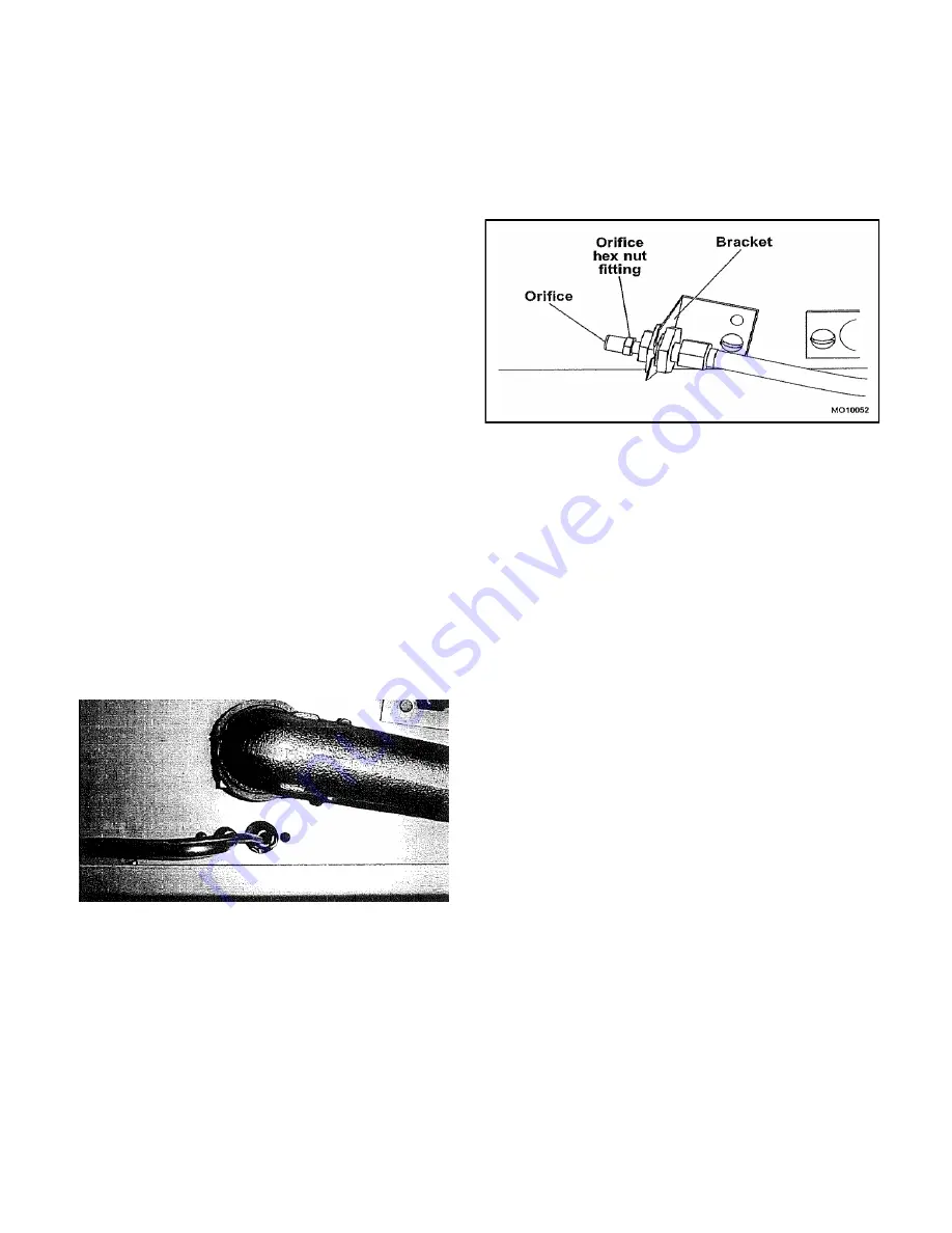
7.  Remove the orifice hex nut fitting from the 

Venturi. 

8.  Remove the orifice from the hex nut fitting. 
 
NOTE: Make sure the pipe joint compound or 
pipe thread sealant that is being used is        
resistant to the corrosive actions of liquefied  
petroleum gases. 
 

9.  Reassemble by reversing procedure. 

WARNING! 
All gas joints disturbed during servicing 
must be checked for leaks. Check with a 
soap and water solution (bubbles). DO NOT 
use an open flame. 

Figure 9. Orifice Assembly 
 
Burner Valve Removal/Replacement 

 
The burner valves are located on the manifold 
behind the control panel cover. 

 
CAUTION: Turn off the gas supply at the 
manual shutoff valve that is next to the 
broiler before attempting to loosen any gas 
connections. 
 

1.  Remove the control panel cover as            

described under COVERS AND PANELS to 
access the burner valve. 

2.  Disconnect the gas line, pilot line, and ther-

mocouple from the back of the burner valve. 

3.  Unscrew the burner valve from the manifold. 
4.  Install the new burner valve. 
 
NOTE: Make sure that the pipe joint compound 
or pipe thread sealant that is being used is     
resistant to the corrosive actions of liquefied   
petroleum gases. 
 
5.  Connect the gas line, pilot line, and        

thermocouple to the back of the valve. 

6.  Turn the main gas shutoff valve to the    

broiler to the ON position. 


WARNING 
All gas joints disturbed during servicing 
must be checked for leaks. Check with a 
soap and water solution (bubbles). DO NOT 

Summary of Contents for E136W36

Page 1: ...85 3342 GAS FIRED BROILERS E36W36 EV136W36 EC36 E43W36 E236W36 EC45 E136W36 E243W36 Please read this manual completely before attempting to install or operate this equipment Notify carrier of damage I...

Page 2: ...EXTINGUISH ALL NAKED FLAMES 3 CONTACT THE LOCAL GAS AUTHORITY IMMEDIATELY THE FOLLOWING INSTRUCTIONS SHOULD BE READ CAREFULLY AS THE MANUFACTURER CANNOT BE HELD RESPONSIBLE FOR ANY DAMAGE TO PROPERTY...

Page 3: ...FETY 18 C36 C45 EXPLODED VIEW 19 C36 C45 PARTS LIST 20 36W36 43W36 EXPLODED VIEW 21 36W36 43W36 PARTS LIST 22 PARTS REMOVAL AND REPLACEMENT PROCEDURES 23 COVERS AND PANELS 23 Venturi Cover 23 Control...

Page 4: ...is not damaged while being moved into the building 1 Visually inspect the exterior of the package and skid or container Any damage should be noted and reported to the delivering carrier immediately 2...

Page 5: ...fold pipe with the burner lit MODEL No Burners broiler only G20 kW G31 kW Total kW E36W36 2 12 3 ea 12 3 ea 4 6 E43W36 3 12 3 ea 12 3 ea 36 9 E136W36 2 12 3 ea 12 3 ea 36 3 EV136W36 2 12 3 ea 12 3 ea...

Page 6: ...e and shall be 4 5 cm per kW in excess of 7kW NOTE 2 Air vents should be of such a size to compensate for the effects of any extract fan in the premises It is also necessary that sufficient room air i...

Page 7: ...e of the burner LOCATION Adequate clearance for service and proper operation must be provided at the front top sides and back The combustion air openings are provided in the front of the unit and must...

Page 8: ...ted at the lower left rear of the broiler Figure 4 On dual broilers each broiler must have a separate regulator NOTE Pipe joint compound or thread sealant that is used should be resistant to action of...

Page 9: ...a rich soap solution or other accepted leak tester around all pipe connections and all other joints Do not use an open flame Absolutely no leakage should occur other wise there is a danger of fire or...

Page 10: ...ure 5 Figure 5 Control Valve Knobs 5 Remove the control valve panel by removing two screws 6 Connect a manometer to the pressure tap provided on the broiler unit gas piping manifold Figure 6 Turn all...

Page 11: ...er this balance is disturbed poor operating characteristics occur An air shutter Figure 8 on the front of each main burner controls the air supply NOTE Pilots should be lit SEE PAGE 12 before adjustin...

Page 12: ...nimum flame when the temperature set on the dial is attained in the oven 1 Light the oven set thermostat to 100 C and allow 5 minutes for the oven temperature to stabilize 2 After oven temperature ris...

Page 13: ...o that the instrument or thermometer reading is in line with the indicator mark Hold plate and tighten screws firmly Turn the calibration plate counter clockwise if the test reading is higher than the...

Page 14: ...rner and pilot gas on or off One control for each burner GRID HEIGHT The grid is set to the desired cooking height by depressing the ball and adjusting the lever up or down Gas Control Lighting Religh...

Page 15: ...and the safety device will disengage within 60 seconds PREHEAT TIME Allow at least five 5 minutes after turning the broiler on from cold before loading the broiler with food to be cooked Check the gre...

Page 16: ...ld with the thermo stat set at the desired temperature before loading the oven with food to be cooked Put the food in quickly and close the door LIGHTING THE OVEN To light the oven 1 Push in the main...

Page 17: ...remove dirt grease or product residue from stainless steel use ordinary soap and water with or without detergent applied with a sponge or cloth Dry thoroughly with a clean cloth To remove grease and...

Page 18: ...ommended that servicing is carried out at regular intervals the frequency of which will vary depending on the installation conditions and usage usually once per year is adequate Servicing must be carr...

Page 19: ...19 C36 C45 EXPLODED VIEW...

Page 20: ...ID IRON RIGHT 4 N A 1602 0 GRID IRON CENTER 5 1601 2 1601 2 GRID IRON LEFT 6 43476 0 43476 0 HANDLE VALVE w o RING 7 11611 4 11611 4 CERAMIC LARGE 7A 28387 8 28387 8 CERAMIC KIT 10 ea 11611 4 Large Ce...

Page 21: ...21 36W366 43W36 EXPLODED VIEW...

Page 22: ...RON CENTER 5 1601 2 1601 2 GRID IRON LEFT 6 43476 0 43476 0 HANDLE VALVE w o RING 7 11611 4 11611 4 CERAMIC LARGE 7A 28387 8 28387 8 CERAMIC KIT 10 ea 11611 4 Large Ceramics 4 ea 11614 9 Ceramic insul...

Page 23: ...er before attempting to loosen any gas connection Venturi Cover Removal of the Venturi cover provides access to the air shutter adjustments and main burner orifices 1 Remove the two screws under the f...

Page 24: ...e front end under the retaining latch Figure 3 Drip Deflector DRIP TRAY AND HORIZONTAL GREASE CONTAINER The drip tray is located below the drip deflector Grease dripping onto the drip deflector runs o...

Page 25: ...cket NOTE Check condition of the pilot injector and replace if damaged 4 Install the new pilot assembly orifice and pilot assembly bracket 5 Connect the gas line to the back of the pilot assembly NOTE...

Page 26: ...und or pipe thread sealant that is being used is resistant to the corrosive actions of liquefied petroleum gases 9 Reassemble by reversing procedure WARNING All gas joints disturbed during servicing m...

Page 27: ...rclockwise from the threaded stud 4 Remove the sleeve from the tube threaded stud assembly 5 Replace the chrome sleeve by placing the s sleeve onto the threaded stud Threaded Stud 1 Turn off the burne...

Page 28: ...sembly using needle nose pliers 7 Replace the compression spring by performing the above steps in reverse order Gear with Bracket 1 Turn off the burners 2 Allow the broiler to cool to room tempera tur...

Page 29: ...or 1 Before adjusting the regulator check the incoming gas line pressure Incoming pressure before the regulator must be 20 mbar for G20 or 27 mbar for G31 2 If incoming pressure is not correct have th...

Page 30: ...urner Venturi in place 6 Remove burner head 7 Clean the burner with a stiff scrubbing brush and shake well to endure that the ports are clear of any debris 8 Reassemble in the reverse order CLEANING B...

Page 31: ...clockwise to level the grid MISCELLANEOUS 1 Wire brush the surface of the grid to remove baked on material wash with hot water dry thoroughly and reassemble 2 Clean out the grease container and wash w...

Page 32: ...ust gas pressure Replace damaged or missing ceramics See Installation Operation manual Perform the BURNER VALVE REMOVAL AND REPLACEMENT PROCEDURE The heat of one or more burners is not uniform over th...

Page 33: ...33...

Page 34: ...8 CERAMIC KIT 10 ea 11611 4 Large Ceramics 4 ea 11614 9 Ceramic Insulators 11A 15352 4 15383 4 HEAT SHIELD 11B 1430 3 1430 3 INSULATION 12 15182 3 15295 1 FIRE BOX FRONT ASSEMBLY 13A 41741 6 41741 6...

Page 35: ...EAR ASSEMBLY 31 32756 5 32756 5 SPRING HANDLE 32 14442 8 14442 8 HANDLE ASSEMBLY BRACKET 33 15244 7 15244 7 CARRIAGE SPRING MTG BRACKET 34 1938 0 1938 0 EYE BOLT 35 3507 6 3507 6 GEAR w ANGLE BRACKET...

Page 36: ...36...

Page 37: ...OR 13 11611 4 11611 4 CERAMIC LARGE 13A 28387 8 28387 8 CERAMIC KIT 10 ea 11611 4 Large Ceramics 4 ea 11614 9 Ceramic Insulators 14 15359 1 15359 1 HEAT SHIELD 15 15223 4 31645 8 OVEN BOTTOM LINER 16...

Page 38: ...04 1 3504 1 SLEEVE 34 3506 8 3506 8 THREADED ROD 35 3503 3 3503 3 TUBE AND GEAR ASSEMBLY 36 23753 1 23753 1 SPRING HANDLE 37 14442 8 14442 8 HANDLE ASSEMBLY BRACKET 38 15244 7 15244 7 BRACKET CARRIAGE...

Page 39: ...d of such possible exposure This warning should be conveyed in a manner so that it is clearly understood by the employee and the employee should be asked if in fact he or she understands the correct m...

Page 40: ...40 The Montague Company 1830 Stearman Avenue P O Box 4954 Hayward CA 94540 4954 P N 42880 9RB WWW MONTAGUECOMPANY COM SAVE THESE INSTRUCTIONS FOR FUTURE USE...

Reviews: