background image

Delta softstart  RevB17  26-9-17 


6.0 ISOLATION 


1


In  an  emergency,  switch  off  at  the  mains  wall  isolator,  or  the  machine’s 
emergency stop button. To release the emergency stop button, turn clockwise. 


7.0 

CLEANING INSTRUCTIONS


NOTE:  

-Cleaning mu

st be carried out by fully trained personnel only.   


-Isolate machine from mains supply before carrying out any cleaning. 
 
-Do not steam clean or use a jet of water, 
 

except in the rotary template drive gear compartment 


All the outer surfaces of the machine should be wiped over with warm soapy water. 

 Do not use any form of caustic detergent or abrasive. 


BETWEEN PRODUCT MIX CHANGES 

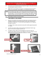
The  hopper,  hopper  pump,  template,  nozzles  etc should  be  removed  from  the 
machine and dismantled for thorough cleaning. 
 

2


Prior  to  removing  the  hopper  or  template,  the  guards  must  be  hinged  up  and 
propped into the appropriate position. 


3


Slacken  template  clamp  strip  nuts  and  remove  fitted  template  from  hopper 
pump  assembly by sliding out to avoid subsequent damage. 


4


To  reduce  weight  and  bulk,  separate  and  remove  hopper  body  from  hopper 
pump  assembly  whilst  still  on  the  machine.  Unscrew  the  nuts  holding  the 
hopper  body  to  the  hopper  pump  to  reveal  the  ‘0’  sealing  ring.  Ensure  seal  is 
not damaged during cleaning. 


5


Unscrew hopper retaining pin and remove hopper pump assembly from 
machine to


separate cleaning area.


ROTARY TEMPLATE 

DRIVE 

FRONT AND REAR GUARDS 

HINGED UP


HOPPER RETAINING PIN


EMERGENCY          

STOP BUTTON


Summary of Contents for DELTA DEPOSITOR 40

Page 1: ...A DEPOSITOR The use of templates and or accessories not produced or supplied by MONO Equipment will invalidate the machine s warranty www monoequip com Enter Serial No here ___________________________...

Page 2: ...Delta softstart RevB17 26 9 17 2...

Page 3: ...OULD BE TAKEN WHEN THE MACHINE COMES TO THE END OF ITS WORKING LIFE ALL PARTS SHOULD BE DISPOSED OF IN THE APPROPRIATE PLACE EITHER BY RECYCLING OR OTHER MEANS OF DISPOSAL THAT COMPLIES WITH LOCAL REG...

Page 4: ...ng a rotary template 10 0 CONTROL PANEL Key diagram 11 0 DESCRIPTION OF CONTROL PANEL FUNCTIONS 12 0 OPERATIONAL CONTROLS Start button Stop button Prime button Auto button Manual button 13 0 PREPERATI...

Page 5: ...ters Subsequent deletion of created programs is only via a password protected screen The DELTA has four axes of controlled movement deposit pump deposit head raise lower tray horizontal travel and noz...

Page 6: ...1225 MAX WIDTH 1193mm 580mm HOPPER 1063mm 450mm HOPPER 1013mm 400mm HOPPER TABLE HEIGHT 825 mm MIN HEIGHT 1370 mm MAX HEIGHT 1485 mm As it is our policy to improve our machines continuously we reserv...

Page 7: ...m deposit that can be made depends on several factors Recipe mixing method template size and deposit speed As a guide the following is the minimum that should be attempted macaroons 6g meringues 3g ch...

Page 8: ...the machine 8 Switch off power at the mains isolator when machine is not in use and before carrying out any cleaning or maintenance ALL CLEANING AND MAINTENANCE OPERATIONS MUST BE MADE WITH MACHINE D...

Page 9: ...1 The hopper hopper pump template nozzles etc should be removed from the machine and dismantled for thorough cleaning 2 Prior to removing the hopper or template the guards must be hinged up and propp...

Page 10: ...tempting reassembly 8 Reassembly is reversal of above procedure TABLE REMOVAL AND CLEANING 1 Removal of the table from the machine for cleaning is not necessary however if required unscrew the two sec...

Page 11: ...gn hopper pump drive gear with drive shaft and slide hopper on support bars until fully up against bulkhead Screw in hopper retaining screw once the hopper is positioned correctly DO NOT OPERATE MACHI...

Page 12: ...cap If gear teeth of template fail to mesh at first attempt lower front and rear hopper guards and press start To rotate the drive gear press then the green button 14 Retry full engagement of templat...

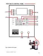
Page 13: ...Delta softstart RevB17 26 9 17 13 5 8 1 4 19 17 18 14 13 16 9 10 15 12 11 Fig 10 DELTA Control panel 10 0 DELTA CONTROL PANEL...

Page 14: ...es with product mix B Aids the engagement of the hopper drive gear into the drive shaft C Aids the engagement of the rotary template drive gear into the machine drive gear D Allows alphabetical charac...

Page 15: ...naming product programs into memory 12 ESCAPE Enables exit from menus to higher level menus and exit from current on screen operation 13 EMERGENCY STOP Immediately isolates all power circuits To relea...

Page 16: ...low negative values where not appropriate 18 ENTER Enters typed and displayed information into product program as well as machine set up program 19 0 9 numeric keys Allows data entry of numerical valu...

Page 17: ...t button 14 primes the pump gears and nozzles with product after the hopper has been loaded with mix and the hopper guards have been closed The deposit motor will run as long as the button is pressed...

Page 18: ...meringue dampen with water The oil or water will help the mix to settle down the hopper walls and prevent air being sucked in 2 Press start button 3 Place a tray under the nozzles to collect initial d...

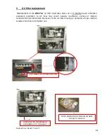
Page 19: ...E ROTARY TEMPLATE DRIVE GEAR HOUSING 1 RESETTABLE MINIATURE CONTACT BREAKERS These are located behind the lower removable panel on the right hand side If a circuit breaker trips out more than once in...

Page 20: ...ise excessive restriction to air flow may result causing insufficient cooling of internal components and electronics Removal of the air filler housing is achieved via two internal screws at the base o...

Page 21: ...rial number on the silver information plate of the machine and on the front cover of this manual UK SERVICE SPARES and OVERSEAS SUPPORT 16 0 SPARES AND SERVICE Queensway Swansea West Industrial Estate...

Page 22: ...Delta softstart RevB17 26 9 17 22 17 0 DELTA DEPOSITOR RECOMMENDED SPARES LIST...

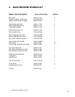
Page 23: ...otor servo amplifier B739 80 001 1 Rack for servo amplifiers B739 09 001 1 Jog motor assy B740 74 001 1 Deposit motor assy B741 74 001 1 Tray motor assy B741 74 002 1 Rotary template motor assy B741 7...

Page 24: ...00200 1 Rotary template drive gear 073 04 00300 1 Rotary template drive shaft 073 04 00400 1 Key rotary template gearbox 073 04 00700 1 Deposit pump drive shaft 073 04 00800 1 Disc spring A900 19 081...

Page 25: ...Drive shaft 073 08 00900 1 Idler shaft 073 08 01000 1 Idler pulley 073 08 01100 2 Drive pulley 073 08 01200 2 Conveyor belt A900 22 101 2 Drive shaft bearing A900 06 245 2 Drive shaft 073 08 00902 1 I...

Page 26: ...ip 073 09 00402 1 End cap drive side 073 09 00500 1 End cap non drive side 073 09 00502 1 End cap bush 073 09 00600 4 Template clamp stud 073 09 01000 4 End cap stud 073 09 01100 4 Hopper stud 073 09...

Page 27: ...Delta softstart RevB17 26 9 17 27 18 0 ELECTRICAL DIAGRAMS...

Page 28: ...Delta softstart RevB17 26 9 17 28...

Page 29: ...Delta softstart RevB17 26 9 17 29...

Page 30: ...Delta softstart RevB17 26 9 17 30...

Page 31: ...Delta softstart RevB17 26 9 17 31...

Page 32: ...Delta softstart RevB17 26 9 17 32...

Page 33: ...Delta softstart RevB17 26 9 17 33...

Page 34: ...Delta softstart RevB17 26 9 17 34...

Page 35: ...Delta softstart RevB17 26 9 17 35...

Page 36: ...Delta softstart RevB17 26 9 17 36...

Page 37: ...Delta softstart RevB17 26 9 17 37...

Page 38: ...sway Swansea West Industrial Park Swansea SA5 4EB UK Tel 01792 561234 Fax 01792 561016 Email mono monoequip com www monoequip com As it is our policy to improve our machines continuously we reserve th...

Reviews: