background image

1

1

2

3

1

2

1

2

6

5

4

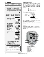
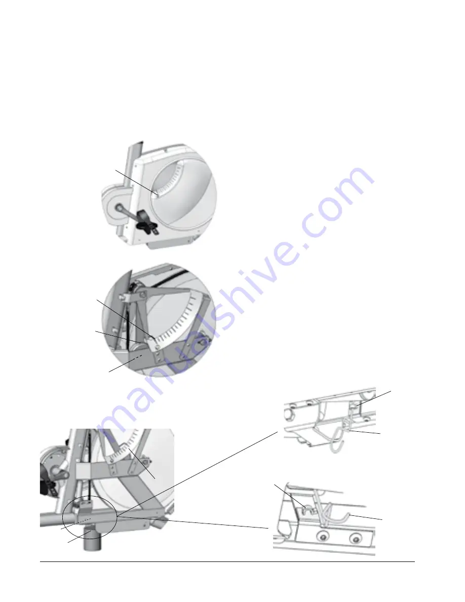
Fig: Calibration mode

1) Hook bracket

2) Calibration hook

Fig: Normal mode

1) Hook bracket

2) Calibration hook

Monark 928 G3 / 928 G3r

 13

Scale - zero adjustment

Connect power to the bike. Loosen possible tension 
in the brake belt by moving the indicator to 0.5 kp. 
Hold it there until the belt feels loose. Then move the 
indicator  to  0  again.  Now  check  if  the  indicator  is 
aligned with the 0-index on the scale.

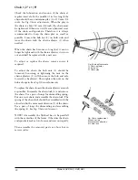
If  adjustment  is  needed,  loosen  the  locknut(1)  and 
then change the position of the scale board, so that it 
will have its 0-index in line with the pointer. Tighten 
the  lock  nut  after  the  adjustment.  See 

Fig:  Scale 

adjustment.

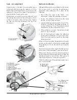
Fig: Scale adjustment

1) Locking screw

Mechanical calibration

Although all Ergometers are calibrated at the factory 
the  user  may  wish  to  verify  this  by  performing  a 
mechanical  scale  calibration.  If  so,  please  do  the 
following:

First,  follow  the  steps  in  the  "Scale  -  zero 

• 

adjustment”. Adjust the pendulum if necessary.

Loosen  the  calibration  hook  from  the  hook 

• 

bracket, see 

Fig: Calibration mode

.

A checked and approved weight(4), 4 kg (Art. No: 

• 

9000-211), attached to the calibration hook (5), 
see 

Fig: Calibration

. Note! The calibration hook 

should always be left in the hook control. 

If the calibration is correct, the indicator should 

• 

point to 4 kp on the scale.

Lift  off  the  weight  and  replace  the  calibration 

• 

hook in the hook bracket, see 

Fig: Normal mode

Note!  The  hook  must  be  inserted  in  the  holder 
during operation.

If there is a deviation, adjust the pendulum to the right 
position  on  the  scale  by  adjusting  the  weight  inside 
the pendulum (2). To do this the left cover must be 
removed. 

To adjust the position of the weight, the locking screw, 
in the center of the pendulum(3), must be loosened.

If the pointer shows too low, the internal weight must 
be moved upwards. If the pointer shows too high, the 
adjustment  weight  is  moved  down.  This  process  is 
repeated until pointer is in the correct position.

Check the calibration of the pendulum weight once a 
year or when needed.

Fig: Calibration

1) The pointer’s 0-position

2) Adjustment weight

3) Locking screw

4) Calibration weight

5) Hook for calibration weight

6) Pointer at 4 kp

Summary of Contents for 928 G2

Page 1: ...EN Manual for 928 G3 928 G3r...

Page 2: ......

Page 3: ...ternative power force display 9 User settings 10 Units 10 Cycle constant 10 Metronome cadence 10 BikeID 10 Base Power 11 Steady State HR 11 Calibration 12 Manual motor control 12 Current potentiometer...

Page 4: ...roof of precision reliability strength and service Those are the reasons why we are now the world leader in cycle ergometers and the market leader in Scandinavia in transport cycles We manufacture dev...

Page 5: ...uction for Calibration in this manual Facts Large well balanced flywheel 20 kg 44 lbs Can be calibrated Adjustable saddle with quick release lever Adjustable handlebar Stable frame solid steel tube Po...

Page 6: ...nd HR When the meter is connected to a computer it turns to passive mode No buttons are active except HEART button to pairing the display and chest belt The socket for the USB connector 1 is shown in...

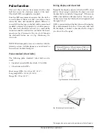
Page 7: ...ike during test Pulse standard chest belts The following pulse standard chest belts can be used Standard uncoded 5K chest belts 5 5 6 kHz Chest belts with ANT Short range ANT 0 6 0 8 m 24 31 Long rang...

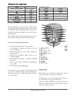
Page 8: ...ge of max HR The workload is rpm independent Display Pedal revolution RPM pedal revolutions min HR bpm TIME min sec Workload WATT alt kpm min Watt Speed km h Distance km Calories KCAL kcal Max HR We r...

Page 9: ...Alternative power force display The meter displays power in watts default If you want to display the power in kpm min instead press the HEART button for 5 seconds Then you can switch between WATT KPM...

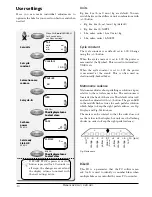
Page 10: ...constant is as default set to 1 00 Change using the button When the cycle constant is set to 1 00 the power is measured at the flywheel This is used in Astrand test YMCA etc When the cycle constant is...

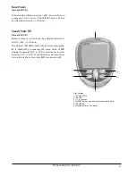
Page 11: ...program or test is active The default value is 25 but can be adjusted with button Steady State HR Except 928 G3r Default value is 3 but can be adjusted between 1 and 10 with button Steady State SS HR...

Page 12: ...manually This is done by pressing in the calibration mode Move the pendulum to the value and hold it still until the potentiometer value stabilized Press ENTER for next step Repeat according to the p...

Page 13: ...ration hook from the hook bracket see Fig Calibration mode A checked and approved weight 4 4 kg Art No 9000 211 attached to the calibration hook 5 see Fig Calibration Note The calibration hook should...

Page 14: ...in Quick Start and the display begins to show count and log values Press START STOP again and the test is completed and the results are displayed on three pages in the display and you can switch betwe...

Page 15: ...approximation for 15 700 W and a cadence of about 50 65 rpm Stop METS program To end the test press START STOP and the results are displayed on three pages Set weight Set age Set max HR Start METS pro...

Page 16: ...ngs Press START STOP for 5 seconds during the test and the test is reset It is recommended not to adjust the braking power after the first three minutes Average value Set weight Set gender Set age Set...

Page 17: ...ive an error message is shown The result is calculated and displayed References Literature Astrand P O Ergometri konditionsprov Monark Sverige strand I Aerobic work capacity in men and women with spec...

Page 18: ...rror message appears Explanations to error messages LO Hr HI Hr Err The end pulse is too low and outside the Astrand tables so no results can be calculated The end pulse is too high and outside the As...

Page 19: ...min 150W 750 kpm min 125W 600 kpm min 100W 1350 225 1200 200 1050 175 1200 200 1050 175 900 150 1050 175 900 150 1350 kpm min 225 W 120 120 135 135 90 90 105 105 135 120 120 135 135 120 120 135 Monark...

Page 20: ...The cadence is 30 for more than 5 seconds When you press START STOP 700 W workload is achieved Set start power Set power increase per step The results are displayed on three pages that you switch bet...

Page 21: ...e display will increase the power at the specified power increase each time the set time has passed and a new countdown begins At the same time you hear a beep The test is automatic after it has been...

Page 22: ...if the test is stopped before the countdown started and only the complete step the data is displayed To see the results that appear on each page see the table on the next page Press ENTER for 5 secon...

Page 23: ...workload and a new countdown starts In the first five seconds of the next steps the display shows test time workload and estimated average HR during the previous step During these five seconds the va...

Page 24: ...if it also indicates irregular pulse If this is the case there are probably a disturbance in the room The disturbance may be electronic fields from power cables elevators lamps etc or other electronic...

Page 25: ...uppl 169 1960 Astrand P O Experimental studies of physical working capacity in relation to sex and age Munksgaard K penhamn 1952 Astrand P O Rodahl K Textbook of Work Physiology McGraw Hill New York 1...

Page 26: ...nk and flywheel are working normally and that no abnormal play or sound exists Play in bearings causes fast wearing and with that follows a highly reduced lifetime Check that the flywheel is placed in...

Page 27: ...whole cord from the bike When assembling a new brake cord first enter one end into the hole in the tension center and tie a knot and let the knot fall into the bigger part of the hole Lock the end of...

Page 28: ...ed Loosening or tightening the nuts on the chain adjusters 1 will then move the hub and axle forward or backward Then tighten the nuts on the hub axle again See Fig Chain adjustments Toreplacethechain...

Page 29: ...heel Remove the axle nut washer chain adjuster and spacer on the freewheel side Replace sprocket adaptor and assemble the new parts in reverse order according to the above The sprocket should be lubri...

Page 30: ...ake belt complete 16 1 9338 19 Stay 4 1 9328 94 Hook for calibration weight 17 1 9328 92 Adapter 5 2 9300 99 Pendulum stop plastic 18 1 9310 55 Motor 6 1 9328 33 Adaptor M20 M16 19 1 9328 96 Bracket f...

Page 31: ...1 9328 132 Locking knob 34 1 9328 188 Power cable 2200 mm 12 1 9328 37 Transport wheel complete pair 1 9328 78 Handlebar compl with handles clamp and locking handle 13 1 9328 6 Support tube rear 35 1...

Page 32: ...Version 1409 Art No 7950 384 KROONS V G 1 SE 780 50 VANSBRO SWEDEN WWW MONARKEXERCISE SE TEL 46 0 281 59 49 40 FAX 46 0 281 719 81...

Reviews: