Monacor TVMP-1600 Instruction Manual Download Page 12

für „Activity Detection“-Alarm), der betroffene Ka-
merakanal, der Zeitpunkt und das Datum.

Tritt ein „Activity Detection“-Alarm in den Betriebsar-
ten „Videorecorder-Wiedergabe“ und „Live-Aufnah-
me“ auf, so wird er vom TVMP-1600 ignoriert.

7.2.1

„Activity Detection“-Alarm zurücksetzen

Wenn die für den „Activity Detection“-Alarm einge-
stellte Alarmdauer (siehe Kap. 8.9, Menü 8: Einstel-
lung „Verweilzeit“) verstrichen ist, werden die oben
beschriebenen Vorgänge beendet.

Zum Beenden des Alarms vor Ablauf der einge-

stellten Zeit die SEL-Taste (12) zweimal, kurz nach-
einander, drücken.

7.3

Alarm bei Bildverlust

Alarm wird ausgelöst, wenn an einem Kameraein-
gang das Videosignal ausfällt, z. B. durch Kamera-
ausfall oder Leitungsunterbrechung.

Wichtig: Alarmauslösung bei Bildverlust ist nur

möglich, wenn diese Alarmfunktion akti-
viert ist (siehe Kap. 8.8, Menü 7: Einstel-
lung „Möglich“ in der Zeile „VLOSS“).

Bei Alarmauslösung werden folgende Funktionen
aktiviert:

Die Leuchtdiode über der Nummerntaste (15) der

entsprechenden Kamera blinkt.

Auf dem Hauptmonitor und auf dem Spot-Monitor

wird im Bild der entsprechenden Kamera die Mel-
dung „VLOSS“ eingeblendet.

Ein akustisches Signal ertönt [sofern der Sum-

mer für diese Alarmfunktion eingeschaltet wurde
(siehe Kap. 8.8, Menü 7: Einstellung „SUM“ in
der Zeile „VLOSS“)]. Das Drücken einer beliebi-
gen Taste beendet den Signalton.

Das Alarm-Relais schaltet [sofern es für diese

Alarmfunktion aktiviert wurde (siehe Kap. 8.8,
Menü 7: Einstellung „RLY“ in der Zeile „VLOSS“)].

Der Spot-Monitor schaltet bei Einzelalarm auf

das Vollbild der entsprechenden Kamera. Bei
Mehrfachalarm schaltet er kontinuierlich mit dem
in Menü 7 unter „Alarm Dauer“ eingestellten

Schaltintervall zwischen den Vollbildern der be-
troffenen Kameras um.
[Dies ist nur möglich, wenn der Spot-Monitor auf
Anzeige dieser Alarmfunktion eingestellt wurde
(siehe Kap. 8.8, Menü 7: Einstellung „HLF“ in der
Zeile „VLOSS“)].

Der Hauptmonitor schaltet auf das im Menü 7 unter

„Alarm Display“ gewählte Alarm-Anzeigeformat:

Ist die Option „4 x 4“ gewählt, schaltet der Mo-

nitor auf das Anzeigeformat „Mehrfachbild 4 x 4“.

Ist die Option „VOLL“ gewählt, schaltet der Mo-

nitor bei Einzelalarm auf das Vollbild-Format der
betroffenen Kamera. Bei Mehrfachalarm schaltet
er kontinuierlich mit dem in Menü 7 unter „Alarm
Dauer“ eingestellten Schaltintervall zwischen den
Vollbildern der betroffenen Kameras um.
[Dies ist nur möglich, wenn der Hauptmonitor auf
Anzeige dieser Alarmfunktion eingestellt wurde
(siehe Kap. 8.8, Menü 7: Einstellung „HPT“ in der
Zeile „VLOSS“)].

Im Alarmprotokoll des Bildschirm-Menüs (siehe

Kap. 8.10, Menü 9: Option „Anzeige Alarmzäh-
ler“) wird die Alarmauslösung registriert: Angege-
ben werden die Art des Alarms (Kennzeichen „V“
für Bildverlust-Alarm), der betroffene Kameraka-
nal, der Zeitpunkt und das Datum.

7.3.1

Bildverlust-Alarm zurücksetzen

Wenn nach dem Bildverlust wieder ein gültiges
Videosignal vorliegt und seit dem Anliegen des gülti-
gen Signals die für den Bildverlust-Alarm eingestell-
te Alarmdauer (siehe Kap. 8.8, Menü 7: Einstellung
„Pause Ohne Video“) verstrichen ist, werden die
oben beschriebenen Vorgänge beendet.

Zum Beenden des Bildverlust-Alarms vor Ablauf

der eingestellten Zeit die SEL-Taste (12) zweimal,
kurz nacheinander, drücken. Die eingeblendete Mel-
dung „VLOSS“ bleibt jedoch für die Dauer des tat-
sächlichen Bildverlustes bestehen.
Hinweis: Ist die Option „Videoverlustverschluss“ ein-

gestellt (siehe Kap. 8.8, Menü 7), lassen
sich die Einblendung „VLOSS“ im betroffe-
nen Kamerabild und die blinkende LED
über der entsprechenden Nummerntaste

(15) nur durch Aufrufen des Bildschirm-
Menüs [d. h. Taste SEL (12) und MENU (9)
nacheinander drücken] zurücksetzen.

8

Änderung der Geräteinstellungen

Der Anwender kann durch die Einstellungsmöglich-
keiten einer Vielfalt von Betriebsparametern den
TVMP-1600 seinen Bedürfnissen entsprechend an-
passen. Sämtliche Einstellungen sind über ein Bild-
schirm-Menü auf dem Hauptmonitor veränderbar.

Zum  Aufrufen des Bildschirm-Menüs die Ta-

sten SEL (12) und MENU (9) nacheinander drücken
[Befindet sich das Gerät in der Betriebsart „Video-
recorder-Wiedergabe“, so muß diese zuerst durch
Drücken der Taste

(10) verlassen werden.] Die

LED über der MENU-Taste leuchtet, und das Haupt-
menü (siehe Kap. 8.1) erscheint.

Bei aktiviertem Paßwortschutz (siehe Kap. 8.10)

erscheint beim Aufrufen des Bildschirm-Menüs an-
statt des Hauptmenüs zunächst folgende Seite:

bzw., wenn als Menüsprache „Englisch“ eingestellt
wurde, die folgende Seite:

Nur nach Eingabe der richtigen Ziffernkombination
gelangt man in das Hauptmenü.
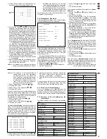
Enter password: * * * *

Enter the 4 digit code
using CAMERA buttons(1–10)

CAM (1–10)

Paßwort eingeben: * * * *

Geben Sie ein 4-stelliges Paßwort
ein. Verwenden Sie dafür die
Kameraauswahltasten(1–10)

CAM (1–10)

[This is only possible if the spot monitor has been
adjusted to the display of this alarm function (see
chapter 8.8, menu 7: setting “S.M.” in the line
“VLOSS”)].

The main monitor switches to the alarm display

format selected in menu 7 under “Alarm Display”:

If the option “4 x 4” is selected, the monitor

switches to the display format “multiple picture
4 x 4”.

If the option “FULL” is selected, the monitor

switches to the full screen format of the camera
concerned in case of individual alarm. In case of
multiple alarm it switches continuously between
the full screen pictures of the cameras concerned
with the switching interval adjusted in menu 7
under “Alarm Dwell”.
[This is only possible if the main monitor has
been adjusted to the display of this alarm function
(see chapter 8.8, menu 7: setting “M.M” in the
line “VLOSS”)].

In the alarm record of the screen menu (see chap-

ter 8.10, menu 9: option “Alarm Count Display”)
the alarm triggering is registered: the kind of alarm
(sign “V” for video loss alarm) is stated, the cam-
era channel concerned, the time, and the date.

7.3.1

Reset of the video loss alarm

If a valid video signal is present again after the video
loss and the alarm duration adjusted for the video loss
alarm has elapsed since the valid signal is present
(see chapter 8.8, menu 7: setting “Video Loss Hold”),
the above-described proceedings are finished.

To stop the video loss alarm before the end of the

adjusted time, press the SEL button (12) shortly
twice in succession. The inserted message “VLOSS”
is, however, maintained for the duration of the actual
video loss.
Note: If the option “Video Loss Latch” is selected

(see chapter 8.8, menu 7), it is only possible
to reset the insertion “VLOSS” in the camera
picture concerned and the blinking LED above
the corresponding numerical key (15) by cal-
ling the screen menu [i. e. by pressing the SEL
(12) and MENU (9) buttons successively].

8

Change of the Unit Settings

The user can match the TVMP-1600 according to
his requirements as there is a great variety of oper-
ating parameters which can be set. All settings can
be changed via a screen menu on the main monitor.

To call the screen menu, press the SEL (12) and

MENU (9) buttons successively. [If the unit is in the
operating mode “video recorder reproduction”, first
press the button

(10) to leave this operating

mode.] The LED above the MENU button lights up,
and the main menu (see chapter 8.1) is displayed.

If the password protection has been activated

(see chapter 8.10), the following page is shown in
the place of the main menu (if “English” has been
selected as menu language) when calling the
screen menu:

Only after the input of the correct number combina-
tion the main menu will be displayed.

For the operation of the screen menu the following
buttons are necessary:
– the cursor buttons “Downwards” 

(2), “Upwards”

(3), “Left” 

(4), and “Right” 

(5)

– the SET button (14)
– the numerical keys (15)
– the MENU button (9)
Not all buttons are available on each menu page.
Therefore, at the lower edge of the respective menu
page those buttons are indicated which are avail-
able for the operation.

All changes made in the screen menu are perma-
nently stored directly after the input confirmation,
i. e. they are maintained even after failure of the
supply voltage.

To  leave the screen menu from the main menu,
press the MENU button (9). If no button is actuated
for approx. 2 minutes, the screen menu is automati-
cally left.
Attention: If the screen menu is called, alarm cases

occurring are disregarded!

8.1

The main menu

If a main menu of another language is displayed in-
stead, the English presentation can be selected via
the following operating steps:

1. Press the numerical key “10” or select the tenth

menu item with the cursor button 

or 

.

2. Press the SET button.
3. With the cursor button 

or 

select according

to the preset language “Englisch”, “Inglese”, or
“Anglais”.

4. Press the SET button to confirm. Now the menu

language “English” is set.

8.1.1

Selecting a menu item

To select a menu item, take the following operating
steps:
1. Press the numerical key marked with the number

of the desired menu item, or select the menu item
with the cursor button 

or 

.

2. Press the SET button. Now the page of the se-

lected menu item is displayed.
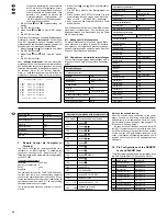
MAIN MENU

1. Time, Date Setup
2. Camera Title
3. Sequence Setup
4. Recording Setup
5. Cameras to Record
6. Alarm Input Setup
7. Alarm Setup
8. Activity Detection Setup
9. Security Setup

10. Menu Language: English

↑ ↓

MENU       SET       CAM(1–10)

Enter password: * * * *

Enter the 4 digit code
using CAMERA buttons(1–10)

CAM (1–10)

12

GB

D

A

CH

Summary of Contents for TVMP-1600

Page 1: ...MODE D EMPLOI ISTRUZIONI PER L USO GEBRUIKSAANWIJZING HANDLEIDING CONSEJOS DE SEGURIDAD SIKKERHEDSOPLYSNINGER SÄKERHETSFÖRESKRIFTER TURVALLISUUDESTA 16 KANAL DUPLEX S W MULTIPLEXER 16 CHANNEL DUPLEX B W MULTIPLEXER TVMP 1600 Best Nr 19 5500 ...

Page 2: ... F B CH I Voordat u inschakelt Wij wensen u veel plezier met uw nieuw toestel van MONACOR Met behulp van bijgaande gebruiksaanwij zing kunt u alle functiemogelijkheden leren kennen Door deze instructies op te volgen zal een slechte werking vermeden worden en zal een eventueel letsel aan uzelf en schade aan uw toestel tengevolge van onzorgvuldig gebruik worden voorkomen U vindt de nederlandstalige ...

Page 3: ... 5 6 7 8 9 10 11 12 13 14 15 1 3 CAM 2 CAM 3 CAM 4 CAM 5 CAM 6 CAM 7 CAM 8 CAM 9 CAM 10 CAM 11 CAM 12 CAM 13 CAM 14 CAM 15 IN OUT REMOTE POWER ALARM DC 12V CAM 16 CAM 1 MAIN SPOT VCR 16 17 18 19 20 21 22 23 24 2 1 2 3 4 5 6 7 8 9 10 11 12 13 14 15 16 SEL 16 Channel B W Duplex Multiplexer TVMP 1600 SET ZOOM 1 MENU LIVE REC ...

Page 4: ...timmter Be triebsparameter 6 Taste zum Schalten auf das Anzeigeformat Mehrfachbild 3 4 Please unfold page 3 Then you can always see the operating elements and connections described Contents 1 Operating Elements and Connections 4 1 1 Front panel 4 1 2 Rear panel 5 2 Safety Notes 5 3 Applications 6 4 Setting up the Unit 6 5 Connecting the Unit 6 5 1 Cameras 6 5 2 Monitors 6 5 3 Video recorder 6 5 4 ...

Page 5: ...sschlitze Dies kann zu einem Defekt des Gerätes führen 1 7 Button for switching to the display format Multiple picture 2 8 8 Button for switching to the display format Multiple picture 4 x 4 9 Button MENU for freezing the present display still picture or unfreezing the frozen display for calling the screen menu first press the SEL button 12 then the MENU button and if a menu item is called for jum...

Page 6: ...ap 10 2 a defect might have occurred after a drop or similar accident 3 there are malfunctions The units must in any case be repaired by author ized personnel If the multiplexer and the power supply unit are used for purposes other than originally intended if they are not connected or operated correctly or not repaired by authorized skilled personnel there is no liability for possible damage For c...

Page 7: ...L DUPLEX CCIR H REVISION C can switch from timelapse recording to real time recording in case of alarm 3 Via an alarm hold input pin 22 the present alarm status is held for the duration of an applied posi tive pulse 5 5 Remote control The TVMP 1600 offers three interfaces for the re mote control serially per RS 232 transmission stand ard serially per RS 485 transmission standard or via an operatin...

Page 8: ...f the re cording in the time multiplex technique and instead recording only the picture of one camera channel with the video recorder To switch to this operating mode press button LIVE REC 14 The LED next to the button lights up Then select the camera to be recorded via the corresponding numerical key 15 The camera must be enabled for the recording ON in the setting menu see chapter 8 6 Menu item ...

Page 9: ...pic tures via the numerical keys Then the LED above the SEL button extinguishes again If not all par tial pictures are to be assigned to the cameras break off the procedure by pressing the SEL but ton the LED above the SEL button extinguishes 2 Press the button 11 to start the automatic se quential switching for the last partial picture on the right below The LED above the button lights up For fur...

Page 10: ...e range zoom In the zoom mode a range of the selected picture in case of multiple pictures the first partial picture is displayed twice enlarged as full screen picture To switch to the zoom mode press the ZOOM but ton 13 The LED next to the button lights up To select the cutout to be enlarged the entire picture is inserted in reduced size A frame inside this picture shows the presently selected cu...

Page 11: ...s siehe Kap 8 10 Menü 9 Option Anzeige Alarmzäh ler wird die Alarmauslösung registriert Angege ben werden die Art des Alarms Kennzeichen M the alarm it is possible to switch to live monitoring with the button 10 7 1 1 Reset of an external alarm If the alarm duration adjusted for the external alarm see chapter 8 8 menu 7 setting External Hold has elapsed the above described proceedings are finished...

Page 12: ... in das Hauptmenü Enter password Enter the 4 digit code using CAMERA buttons 1 10 CAM 1 10 Paßwort eingeben Geben Sie ein 4 stelliges Paßwort ein Verwenden Sie dafür die Kameraauswahltasten 1 10 CAM 1 10 This is only possible if the spot monitor has been adjusted to the display of this alarm function see chapter 8 8 menu 7 setting S M in the line VLOSS The main monitor switches to the alarm displa...

Page 13: ...heit 10 Menusprache Deutsch MENÜ SET CAM 1 10 8 2 Menu item 1 Time Date Setup On the menu page TIME AND DATE settings con cerning date and time can be made Display decides if date and time are inserted in the upper screen edge of the main monitor ON or not OFF 1 Select Display with button or 2 Press the SET button 3 Adjust ON or OFF with button or 4 Press the SET button Date Format decides the way...

Page 14: ...12 12 5 5 13 13 6 6 14 14 7 7 15 15 8 8 16 16 MENÜ SET CAM 1 16 8 4 Menu item 3 Sequence Setup On the menu page SEQUENCE SETUP the settings for the automatic sequential switching of pictures see chapter 6 2 Selecting display formats are made For each camera an individual dwell time of 1 s up to 60 s can be fixed via the items 1 16 Cameras without dwell time OFF are skipped during the automatic seq...

Page 15: ...ücken Zum Einstellen des Parameters Alarmbetrieb 1 Mit der Taste oder Alarmbetrieb anwählen 2 Die SET Taste drücken AUFZEICHNUNG EINRICHTEN Externer Ausloser AUS VCR Typ STANDARD VHS Normalbetrieb 003 RT Stunden Alarmbetrieb 003 RT Stunden MENÜ SET TLS2000P Sanyo TLS1500P 2500P Sanyo SVT124P Sony SVT1000P Sony SVTS3000P Sony USER DEFINED any desired video re corder independent of the manufacturer ...

Page 16: ...ble to define for each alarm input of the 16 cam era channels if it is admitted and if yes which alarm contact type is used Via the items 1 16 it is possible to decide for each alarm input see pin configuration of the ALARM jack 23 in chapter 10 if the input is locked OFF or admitted for the reception from an external alarm sensor If the alarm input is to be admitted select the alarm contact type ...

Page 17: ...HPT HLF AUF External ON ON ON ON ON INT DSS ON OFF OFF OFF OFF INT VLOSS ON ON ON OFF OFF Alarm Display 4x4 Alarm Dauer 03s Extern Pause 20s Alarm Klinke OFF Pause Ohne Video 20s Videoverlustverschluss OFF Further alarm settings on this menu page Alarm Display indicates the display format for the main monitor in case of alarm It is possible to select between the following settings 4 x 4 All 16 cam...

Page 18: ...t aufzeichnen AN Verweilzeit 05 Sekunden Detektionsmatrix Kamera 1 MENÜ SET CAM 1 16 1 Select Activity Hold Time with button oder 2 Press the SET button 3 Adjust the desired value with button or 4 Press the SET button Via the submenu Activity Grids the zones which are to be sensible for the motion detection can in dividually be selected for each camera in a grid of 16 x 12 points 1 Select Activity...

Page 19: ...n 2 Die SET Taste drücken 3 Mit der Taste oder die gewünschte Nummer einstellen 4 Die SET Taste drücken Über die Option Werkeinstellung lassen sich sämtliche Geräteeinstellungen auf die vom Werk vor eingestellten Werte zurücksetzen siehe Kap 8 12 Übersicht der Hersteller Voreinstellungen Achtung Die Aktivierung dieser Option löscht alle vom Benutzer vorgenommenen Einstel SICHERHEIT Paßwort AUS Neu...

Page 20: ...The command record of the TVMP 1600 is based on the fact that there are corresponding character codes for the operating buttons in each case Except for the commands concerning the unit addressing all commands start with a slash The two following characters determine the function The following table states an overview of the com mands Notes on the unit addressing After the unit has been connected t...

Page 21: ...al outputs feed through outputs 16 x BNC Main monitor output BNC Spot monitor output BNC Video recorder input BNC Video recorder output BNC Alarm inputs output VCR synchronization input 25 pole SUB D jack Remote RS 232 RS 485 25 pole SUB D jack Power supply low voltage jack coaxial with 2 1 mm pin centre contact positive pole According to the manufacturer Subject to change 1 13 25 14 21 GB D A CH ...

Page 22: ...ftfeuchtigkeit 10 90 nicht kondensie rend Stromversorgung 12 V 1 A über beiliegen des Steckernetzgerät an 230 V 50 Hz 25 VA Abmessungen B x H x T 432 x 44 x 310 mm Gewicht 2 7 kg Anschlüsse Kamera Eingänge 16 x BNC automatische Impedanzanpassung Kamerasignal Ausgänge Durchschleifausgänge 16 x BNC Hauptmonitor Ausgang BNC Spot Monitor Ausgang BNC Videorecorder Eingang BNC Videorecorder Ausgang BNC ...

Page 23: ...roit pour sélectionner certains paramè tres de fonctionnement Vi preghiamo di aprire completamente la pagi na 3 Così vedrete sempre gli elementi di co mando e i collegamenti descritti Indice 1 Elementi di comando e collegamenti 23 1 1 Pannello frontale 23 1 2 Pannello posteriore 24 2 Avvertenze 24 3 Possibilità d impiego 25 4 Collocamento dell apparecchio 25 5 Collegamento dell apparecchio 25 5 1 ...

Page 24: ...branchez le bloc secteur immédiatement lorsque 1 des dommages sur le multiplexer ou le bloc secteur apparaissent 1 9 Tasto MENU per bloccare la visualizzazione attuale imma gine ferma e per sbloccare la visualizzazione bloccata per chiamare il menù sullo schermo premere prima il tasto SEL 12 quindi il tasto MENU e con un punto del menù presente per ritorna re nel menù principale oppure trovandosi ...

Page 25: ...scorretto o di riparazione non a regola d arte del multiplexer o dell alimentatore non si as sume nessuna responsabilità per eventuali danni Se si desidera eliminare gli apparecchi definitiva mente consegnarli per lo smaltimento ad un isti tuzione locale per il riciclaggio 3 Possibilità d impiego Il multiplexer video b n TVMP 1600 è stato realizzato per l impiego in impianti di sorveglianza e d al...

Page 26: ...6 CHANNEL DUPLEX CCIR H REVISION C 5 5 Telecomando Il TVMP 1600 offre tre possibilità per il telecomando tramite linea seriale RS 232 tramite linea seriale RS 485 oppure tramite un unità di comando opzionale In tutti casi il collegamento è fatto con la presa Sub D a 25 poli REMOTE 19 Per la pedinatura vedi cap 10 Con le interfacce RS 232 e RS 485 è possibile pilotare il TVMP 1600 da un computer o ...

Page 27: ...ière inser 1 1 1 1 1 1 1 re deve essere stata abilitata alla registrazione AC CESO e deve fornire effettivamente un segnale video altrimenti la registrazione dal vivo viene inter rotta Se è stato scelto il numero di una telecamera valida il LED vicino al tasto LIVE REC lampeggia e ogni 20 secondi si sente un breve segnale acustico se tale funzione è stata attivata nel menù di im postazione per più...

Page 28: ...di cap 8 4 Me nù 3 Sequenze Una nuova pressione del ta sto ferma la funzione e il LED si spegne 6 2 5 Immagine multipla 3 x 3 Nella modalità immagine multipla 3 x 3 si vedono nove immagini a 1 9 della grandezza dell immagine intera 1 Per attivare il formato di visualizzazione 3 x 3 pre mere il tasto 5 Il LED sopra il tasto si accen de Con ogni nuova pressione del tasto le im magini passano alle no...

Page 29: ...rme commute s il a été activé pour cette fonction d alarme voir chap 8 8 menu 7 réglage RLY dans la ligne Externe 1 1 1 passa nella rappresentazione precedente N B La successione sequenziale e il bloccaggio freeze dell immagine non sono possibili nella modalità zoom La pressione di un tasto numerico 15 interrompe la modalità zoom e l immagine della telecamera del numero pre muto viene rappresentat...

Page 30: ... menu 7 sous Vitesse Alarme entre les ima ges plein écran des caméras concernées Dans l image de la caméra correspondante le message M est inséré N B Se è stata selezionata l opzione Visualizza zione mess allarme vedi cap 8 8 menù 7 la scritta sul monitor ALARM nell immagine interessata e il LED lampeggiante sopra il re lativo tasto numerico 15 possono essere re settati solo chiamando il menù prem...

Page 31: ...iversité des paramètres de fonctionnement Tous les régla ges peuvent être changés via un menu sur l écran du moniteur principal Pour appeler le menu écran enfoncez les tou ches SEL 12 puis MENU 9 Si l appareil est en mode lecture magnétoscope d abord enfoncez la touche 10 pour quitter ce mode de fonctionne ment La LED au dessus de la touche MENU brille le menu principal voir chapitre 8 1 s affiche...

Page 32: ...elezionare il menù con il tasto o 2 Premere il tasto SET Appare la pagina richiesta 8 2 Menù 1 Data e ora La pagina DATA E ORA permette l impostazione della data e dell ora Display per determinare se la data e l ora devono essere visibili sul bordo superiore del monitor princi pale ACCESO oppure no SPENTO 1 Selezionare Display con il tasto o 2 Premere il tasto SET 3 Con il tasto o impostare ACCESO...

Page 33: ... Z a b c d e f g h i j k l m n o p q r s t u v w x y z spazio 0 1 2 3 4 5 6 7 8 9 4 Dopo l impostazione del titolo premere il tasto SET 5 Per le altre telecamere eseguire gli stessi passi da 1 a 4 Per abbandonare la pagina e ritornare nel menù principale premere il tasto MENU 8 4 Menù 3 Sequenze Alla pagina SEQUENZE si imposta la successione automatica delle immagini vedi cap 6 2 Selezio nare i fo...

Page 34: ... Enfoncez la touche SET CONFIGURATION ENREGISTREMENT Déclencheur externe ARRET Type scope STANDARD VHS Mode Normal 003 RT Heures Mode Alarme 003 RT Heures MENU SET SRL900E JVC SRL901E JVC BR 9020E JVC SR S970E JVC HS5440E Mitsubishi HS5168E Mitsubishi HS5300E Mitsubishi HS7168E Mitsubishi AG6040E 6730E Panasonic AGTL700 Panasonic AGTL300 Panasonic TL 720HR Philips SRT600 Sanyo SRT672 Sanyo TLS924P...

Page 35: ...mera se devono essere registrate ACCESO o no SPENTO le sue immagini 1 Selezionare la telecamera desiderata con il tasto o o con il relativo tasto numerico 2 Premere il tasto SET 3 Con il tasto o impostare ACCESO o SPENTO 4 Premere il tasto SET N B Se per una telecamera è stata scelto AC CESO l immagine della telecamera viene in viata al videoregistratore solo se al relativo in gresso si riconosce ...

Page 36: ...NY si registrano sia le telecamere con allarme scattato tramite segnalatori esterni che le telecamere con allarme scattato dal segna latore di movimento interno UCD unchanged invariato La composizione del segnale video multiplex per la registrazione non cambia nel caso di allarme 1 Selezionare la funzione d allarme Esterno DSS o VLOSS con il tasto o 2 Premere il tasto SET 3 Con il tasto o selezion...

Page 37: ...on peut commuter pour chaque caméra séparément la reconnaissance d ac DETECTION ACTIVITE Activité Caméra 1 2 3 4 15 16 Sélection Activité MARCHE Durée Activité 05 Secondes Grilles Activité Caméra 1 MENU SET CAM 1 16 1 Selezionare Activity Camera con il tasto o 2 Premere il tasto SET 3 Attivare o disattivare il riconoscimento di un atti vità per le telecamere premendo i tasti numerici delle rispett...

Page 38: ...r Nouveau Code Validation Code Numéro unité 01 Initialisation par défault NON Verrouillage ARRET Affichage compteur alarme MENU SET CAM 1 10 Ο Ο Ο Ο Ο Ο Ο Ο Ο Ο Ο Ο Ο Ο Ο Ο Ο Ο Ο Ο Ο Ο Ο Ο Ο Ο Ο 2 Premere il tasto SET 3 Con i tasti numerici da 1 a 10 impostare una com binazione di quattro cifre il tasto con il numero 10 significa qui la cifra 0 Le cifre impostate non vengono visualizzate sul monit...

Page 39: ...e s affiche 3 En enfonçant la touche SET tous les enregis trements d alarme peuvent être annulés S il n y a pas d enregistrements d alarme PAS D ALAR ME est affiché 4 Pour quitter le dossier d enregistrements d alar me enfoncez la touche MENU Pour quitter la page retournez au menu principal avec la touche MENU Pour quitter le menu d écran à partir du menu principal enfoncez la touche MENU une nouv...

Page 40: ...presa tensioni piccole coas siale gambo 2 1 mm contat to centrale positivo Dati forniti dal costruttore Con riserva di modifiche tecniche 1 13 25 14 40 I F B CH Préréglages Heures été hiver ARRET Format date EURO DD MM YY Affichage MARCHE Réglage auto NON Durée affichage 3 s Affichage MARCHE Titres caméras numéros des caméras Mode alarme 3 heures Mode normal 3 heures Type scope STANDARD VHS Déclen...

Page 41: ...bloc secteur livré relié au secteur 230 V 50 Hz 25 VA Dimensions l x h x p poids 432 x 44 x 310 mm 2 7 kg Branchements Entrées caméra 16 x BNC adaptation automati que d impédance Sorties signaux de caméras passage des signaux 16 x BNC Sortie moniteur principal BNC Sortie moniteur spot BNC Entrée magnétoscope BNC Sortie magnétoscope BNC Entrées sortie alarme entrée impulsion synchron VCR prise SUD ...

Page 42: ...e schakelen resp naar live bewaking terug te schakelen Om naar Opnamevoorbeeld weergave van de beelden in het originele opnameformaat te scha kelen drukt u eerst op de toets SEL 12 vervol gens op toets 11 Toets om de automatische doorschakeling se quentieschakeling te starten resp te stoppen 12 Toets SEL om een alarm te resetten druk tweemaal op de toets om de gewenste weergave voor de spotmoni to...

Page 43: ...ergelijke met de synchronisatie ingang van de TVMP 1600 pin 20 van jack ALARM 23 zie hoofdstuk 10 Zie ook hoofdstuk 8 5 Menu item 4 De opname afregelen Opmerking De synchronisatie van multiplexer en videorecorder via een stuurleiding is niet absoluut noodzakelijk De multi plexer kan ook uitsluitend via de over eenkomstige instellingen in het beeld schermmenu hoofdstuk 8 5 aan de opnamemodus van de...

Page 44: ...equentie schakeling de LED gaat uit 1 1 1 1 1 1 6 2 3 Beeld in beeld 2 met vier ingevoegde beelden In de modus Beeld in beeld 2 wordt één camera als schermvullend beeld weergegeven met onderaan ingevoegd de beelden van de vier andere camera s op formaat 1 16 van het volledige scherm 1 Druk op de toets 3 om naar de modus Beeld in beeld 2 te schakelen De LED boven de toets licht op Telkens als u op ...

Page 45: ...ertoets om een schermvullend beeld van een camera te selecteren resp druk op de toets 11 voor de automatische doorschakeling sequentieschakeling De selectiemodus voor de spot monitor blijft in gesteld tot opnieuw op de toets SEL gedrukt wordt 1 1 1 1 1 1 1 7 Alarmfuncties De multiplexer heeft drie verschillende alarmfuncties extern alarm activering van het alarm door ex tern alarmsensor Activity D...

Page 46: ... VLOSS De hoofdmonitor schakelt naar het alarmweer gaveformaat dat in het menu 7 onder Alarm Dis play geselecteerd is Bij selectie van de optie 4 x 4 schakelt de mo nitor naar het beeldformaat mozaïekbeeld 4 x 4 Bij selectie van de optie FULL schakelt de monitor bij enkelvoudig alarm naar het scherm vullend beeld van de betreffende camera Bij meervoudig alarm schakelt de monitor constant met de in...

Page 47: ...ght Saving OFF DATE FROM TO START 05 04 02 00 03 00 STOP 30 08 02 00 01 00 MENU SET 5 Volg dezelfde procedure stappen 1 4 voor de overige camera s Om de pagina te verlaten springt u met de toets MENU terug naar het hoofdmenu 8 4 Menu item 3 De sequentieschakeling instellen Op de menupagina SEQUENCE SETUP worden instellingen voor de automatische beelddoorschake ling zie hoofdstuk 6 2 Beeldformaten ...

Page 48: ...r de opname 1 Selecteer de gewenste camera met de toets of of met de overeenkomstige nummertoets 2 Druk op de toets SET 3 Stel ON of OFF in met de toets of 4 Druk op de toets SET Opmerking Indien voor een camera de instelling ON geselecteerd is wordt het beeld van deze camera enkel naar de video recorder gestuurd wanneer op de be treffende camera ingang een video signaal gedetecteerd wordt Onderaa...

Page 49: ...Bewegingsdetectie Op de menupagina ACTIVITY DETECTION SETUP worden instellingen van de geïntegreerde bewe gingsdetector doorgevoerd ACTIVITY DETECTION Activity Camera 1 2 3 4 15 16 Activity Select ON Activity Hold Time 05 Seconds Activity Grids Camera 1 MENU SET CAM 1 16 Onder Activity Camera kan u voor elke camera de activiteitsdetectie afzonderlijk inschakelen het cameranummer wordt weergegeven ...

Page 50: ... of 4 Druk op de toets SET Via Alarm Count Display kan u het alarmproto col oproepen Hierin krijgt u een overzicht van alle alarmactiveringen van het toestel Vermeld worden de betreffende alarmfunctie die geactiveerd werd A bij een extern alarm M bij Activity Detection alarm V bij beeldverlies alarm het betreffende camerakanaal het tijdstip en de datum van de ac tivering van het alarm 1 Selecteer ...

Page 51: ... signaal gemeenschappelijke massa Uitgang potentiaalvrij relais met wis selcontact NO NC max schakelbelasting 24 V 1 A enkel Ohmse belastingen Algemeen Omgevingstemperatuur 0 35 C Luchtvochtigheid 10 90 niet condense rend Voedingsspanning 12 V 1 A via meegeleverde netadap ter op 230 V 50 Hz 25 VA Afmetingen B x H x D 432 x 44 x 310 mm Gewicht 2 7 kg Aansluitingen Camera ingangen 16 x BNC automatis...

Page 52: ... Cuando se retiran definitivamente el multiplexor y el alimentador del servicio debe depositarse en una fábrica de reciclaje adaptada E DK 16 kanals duplex s h multiplexer Læs nedenstående sikkerhedsoplysninger opmærk somt igennem før ibrugtagning af enhederne Bort set fra sikkerhedsoplysningerne henvises til den engelske tyske franske eller italienske tekst Vigtige sikkerhedsoplysninger Multiplex...

Page 53: ...hyvä ja huomioi aina seuraavat turvallisuutta koskevat ohjeet ennen laitteen käyttöön ottoa Katso käyttöön liittyviä ohjeita Saksan Englannin Rans kan tai Italian kielisistä ohjeista jos tarvitset lisää tie toa laitteen käytöstä Turvallisuudesta Tämä multiplekseri ja laitteen mukana toimitettu pistokkeella kytkettävä virtalähde vastaa direktiiviä 89 336 EEC sähkömagneettisesta yhteensopivuu desta ...

Page 54: ...Copyright by INTER MERCADOR GmbH Co KG Bremen Germany All rights reserved MONACAOR International www monacor com 10 00 02 ...

Reviews: