


6
Alarmfunktionen
Ein Alarmmelder mit NO-Kontakt kann direkt mit
einer Kamera TVCCD-40 verbunden oder – bei Ver-
wendung einer anderen Kamera – über den optional
erhältlichen Adapter TV-40JB an einen Kamera-
kanal des Monitors angeschlossen werden (siehe
Kap. 4.3.4).
Bei Alarmauslösung schaltet das Gerät in den
Alarmmodus:
- Ist der Summer aktiviert [Schalter „BELL“ (13) auf
„ON“], ertönt für 4 Sekunden ein Signalton.
- Bei Alarmauslösung über einen Alarmmelder,
schaltet der Monitor auf Vollbilddarstellung der
betreffenden Kamera.
Bei Alarmauslösung über mehrere Alarmmelder,
schaltet das Gerät alle 2 Sekunden zwischen den
Vollbildern der betreffenden Kameras hin und her
[solange bis für jede der betroffenen Kameras die
im Bildschirm-Menü eingestellte Alarmdauer (sie-
he Kap. 7.2) abgelaufen ist].
- Für den betreffenden Kamerakanal blinkt die
Meldung „ALARM“ auf dem Bildschirm.
- Die rote LED „CALL“ (7) und die LED für den
betreffenden Kamerakanal blinken.
- Das Alarmrelais (26) schaltet und aktiviert die am
Alarmausgang angeschlossenen Geräte (z. B.
Videorecorder, Alarmgeber).
Beendigung des Alarms
Der Alarm erlischt nach Ablauf der im Bildschirm-
Menü eingestellten Alarmdauer (siehe Kap. 7.2),
und der Monitor schaltet in seinen vorherigen
Betriebszustand zurück. Er läßt sich aber auch vor-
zeitig durch Drücken der Taste „Q/A“ (3) bzw. einer
der Tasten „1 – 4“ (4) abschalten.
7
Programmieren des Monitors
Zum Aufrufen des dreiseitigen Bildschirm-Menüs die
Taste „MENU NEXT“ (2) drücken: die Menüseite 1
wird auf dem Bildschirm eingeblendet.
Hinweis: Befindet sich das Gerät beim Aufrufen
des Bildschirm-Menüs im automatischen
Umschaltbetrieb, erfolgt keine Umschal-
tung der Kamerabilder, solange das Me-
nü aufgerufen ist.
Das Bildschirm-Menü wird automatisch beendet,
wenn nach Ablauf von 2 Minuten keine Einstellung
vorgenommen wurde. Das Gerät schaltet dann in
seinen vorherigen Betriebsmodus zurück.
Alle Einstellungen im Bildschirm-Menü werden über
die
vier
Tasten , ,
+
und
-
(4) auf der Geräte-
vorderseite durchgeführt:
Mit den Cursor-Tasten
und
werden die Ein-
gabefelder angewählt:
Taste
: Cursor bewegt sich vertikal über die Ein-
gabefelder der Menüseite
Taste : Cursor bewegt sich horizontal über die
Eingabefelder der Menüseite
Das gerade aktivierte Eingabefeld blinkt und signa-
lisiert somit, daß die Einstellung dieses Feldes über
die Taste
+
(Durchlauf der Werte in aufsteigender
Reihenfolge) oder die Taste
-
(Durchlauf der Werte in
absteigender Reihenfolge) verändert werden kann.
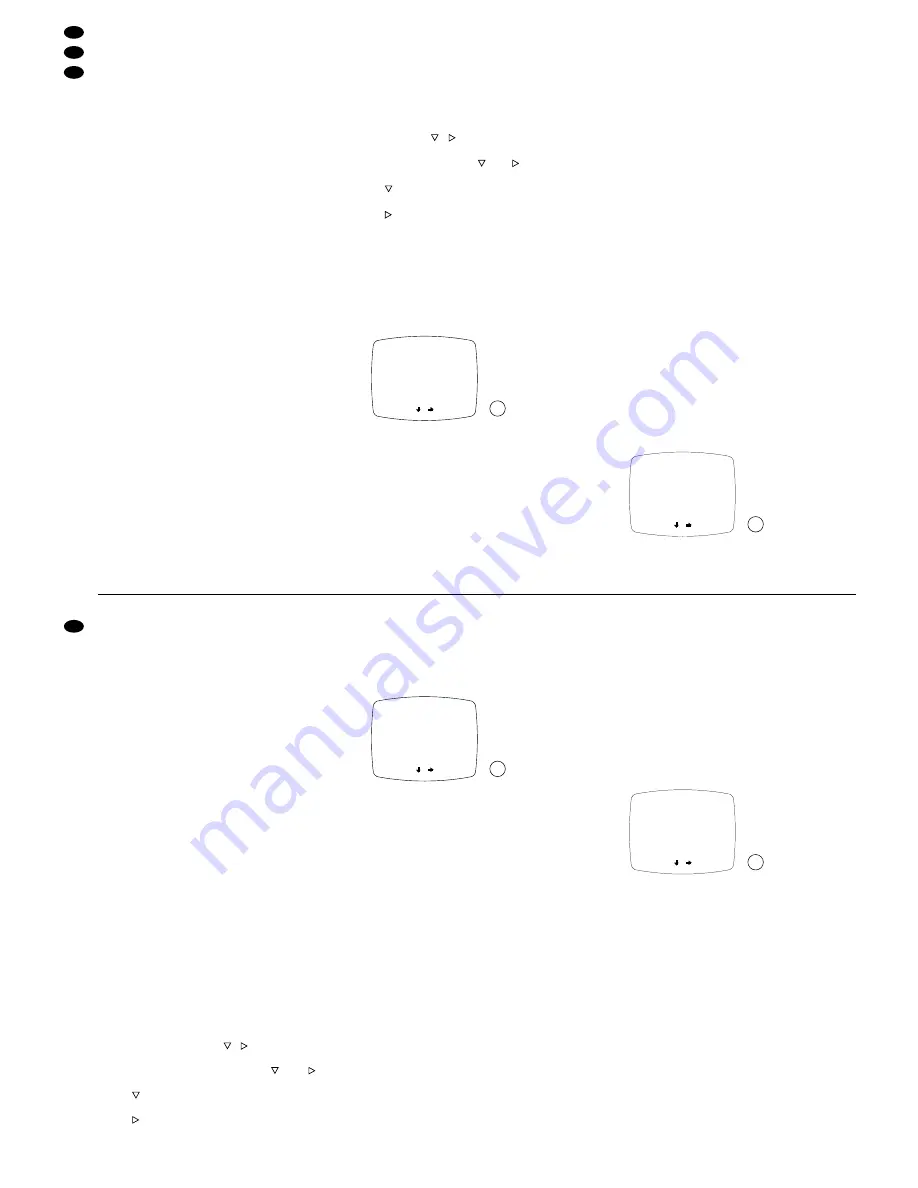
7.1 Menüseite 1: Datum und Uhrzeit einstellen
1) Für die Überwachung über den Monitor CDM-
1440 bzw. CDM-1740 und die Aufzeichnung über
einen Recorder an der Buchse „VCR OUT“ (25)
bzw. „VCR“ (17) können Datum und Uhrzeit auf
dem Bildschirm eingeblendet werden.
Zum Einblenden von Datum und Uhrzeit das
Eingabefeld in der Zeile „DISPLAY“ auf „ON“ stel-
len. Ist eine Einblendung nicht erwünscht, muß
das Eingabefeld auf „OFF“ stehen. Mit der Taste
+
oder
-
kann zwischen „ON“ und „OFF“ umge-
schaltet werden.
2) Zum Einstellen des Formats, mit dem das Datum
angezeigt wird, die Zeile „DATE FORMAT“ an-
wählen. Mit der Taste
+
oder
-
kann zwischen den
drei verfügbaren Formaten umgeschaltet werden:
USA-Format „US“ =
MM-DD-YY (Monat-Tag- Jahr)
Europa-Format „EURO“ =
DD-MM-YY (Tag-Monat-Jahr)
Asien-Format „ASIA“ =
YY-MM-DD (Jahr- Monat-Tag)
Beispiel: Der 1. Dezember 1999 würde in den drei
Formaten folgendermaßen dargestellt werden:
„US“
= 12-01-99
„EURO“ = 01-12-99
„ASIA“ = 99-12-01
3) Zum Einstellen der Uhrzeit in die Zeile „TIME“
springen, und den Teil der Zeitangabe anwählen,
der geändert werden soll („HH“ = Stunden, „MM“
= Minuten, „SS“ = Sekunden). Durch Drücken der
Taste
+
oder
-
die aktuelle Uhrzeit einstellen.
4) Zum Einstellen des Datums in die Zeile „DATE“
springen, und den Teil der Datumsangabe an-
wählen, der geändert werden soll. (Die Datums-
angabe erfolgt gemäß dem in der Zeile „DATE
FORMAT“ eingestellten Format.) Durch Drücken
der Taste
+
oder
-
das aktuelle Datum einstellen.
Nach dem Durchführen der Einstellungen auf Menü-
seite 1 durch Drücken der Taste „MENU NEXT“ (2)
die nächste Menüseite aufrufen.
7.2 Menüseite 2: Bild-Verweildauer und Alarm-
dauer einstellen
1) Die Bild-Verweildauer im automatischen Um-
schaltbetrieb (siehe Kap. 5.2.2) kann separat für
D
E
DW LL ,
CA 1 : 03
CA2 : 03
CA 3 : 03
CA4 : 03
QUA
: 03
AL A
TI ME
RM
AL A
TI ME
R M
: 20
NEXT
-
+
DATE
DATE:
DATE
,
: ON
:
FORMAT
EURO
TI ME:
T I M E
NEXT
-
+
:
:
-
-
DISPL AY
HH MM SS
DD MM YY
duration set in the screen menu (see chap 7.2) is
expired].
- On the screen, the message “ALARM” is flashing
for the corresponding camera channel.
- The red LED “CALL” (7) and the LED for the
corresponding camera channel are flashing.
- The alarm relay (26) responds and activates the
units connected to the alarm output (e. g. video
recorder, alarm devices).
End of the alarm
The alarm stops after the alarm duration set in the
screen menu is expired (see chap. 7.2), and the
monitor switches back to its former operating mode.
However, it can also be switched off earlier by press-
ing the button “Q/A” (3) or one of the buttons “1 to 4”
(4).
7
Programming the Monitor
For calling the three-page screen menu, press the
button “MENU NEXT” (2): menu page 1 is displayed
on the screen.
Note: If the unit is in the automatic change-over
mode when the screen menu is called, no
change-over of the camera pictures will take
place as long as the menu is displayed.
The screen menu is automatically cleared from the
screen if no adjustment has been made after 2 min-
utes. The unit then switches back to its former oper-
ating mode.
Any adjustment in the screen menu is made by
means of the four buttons
,
,
+
and
-
(4) at the
front of the unit:
By means of the cursor buttons
and
, the
input fields are selected:
Button
: Cursor moves vertically across the input
fields on the menu page
Button : Cursor moves horizontally across the
input fields on the menu page
The input field currently activated is flashing to
signalize that the adjustment of this field can be
changed via the button
+
(values in ascending
order) or the button
-
(values in descending order).
7.1 Menu page 1:
Setting the date and the time
1) For surveillance via the monitor CDM-1440 (or
CDM-1740) and recording via a recorder at the
jack “VCR OUT” (25) or “VCR” (17), the date and
the time can be displayed on the screen.
To display the date and the time, set the input
field in line “DISPLAY” to “ON”. If a display is not
desired, the input field must be set to “OFF”. The
button
+
or
-
switches from “ON” to “OFF” and
vice versa.
2) For setting the format in which the date is indi-
cated, select the line “DATE FORMAT”. The but-
ton
+
or
-
switches between three available for-
mats:
American format “US” =
MM-DD-YY (month-day-year)
European format “EURO” =
DD-MM-YY (day-month-year)
Asian format “ASIA” =
YY-MM-DD (year-month-day)
Example: December 1st, 1999 would be indicated
in the three formats as follows:
„US“
= 12-01-99
„EURO“ = 01-12-99
„ASIA“ = 99-12-01
3) For setting the time, go to line “TIME” and select
the part of the time indication which is to be
changed (“HH” = hours, “MM” = minutes, “SS” =
seconds). Set the current time by pressing the
button
+
or
-
.
4) For setting the date, go to line “DATE” and select
the part of the date indication which is to be
changed. (The date indication is made according
to the format selected in the line “DATE FOR-
MAT”.) Set the current date by pressing the but-
ton
+
or
-
.
After the adjustments on menu page 1 have been
made, call the next menu page by pressing the but-
ton “MENU NEXT” (2).
7.2 Menu page 2: Setting the dwell time of the
pictures and the alarm duration
1) The dwell time of the pictures in automatic
change-over mode (see chapter 5.2.2) can be
adjusted separately for each camera channel,
and the quad picture from 0 to 60 seconds.
For camera 1 (“CA1”), adjust the desired dwell
time by pressing the button
+
or
-
. Then select
the other cameras (“CA2 to CA4”) and the quad
picture (“QUAD”) successively, and adjust the
dwell time for each picture. If a picture is to be
skipped, enter 0 seconds into the corresponding
input field.
2) The alarm duration, i. e. the period of time for
which the unit is in alarm mode after an alarm
triggering (see chapter 6), can be adjusted from
4 to 60 seconds.
For setting the alarm duration, go to line
“ALARM TIME” and adjust the desired value with
the button
+
or
-
.
After the adjustments on menu page 2 have been
made, call the next menu page by pressing the but-
ton “MENU NEXT” (2).
D
E
DW LL ,
CA 1 : 03
CA2 : 03
CA 3 : 03
CA4 : 03
QUA
: 03
AL A
TI ME
RM
AL A
TI ME
R M
: 20
NEXT
-
+
DATE
DATE:
DATE
,
: ON
:
FORMAT
EURO
TI ME:
T I M E
NEXT
-
+
:
:
-
-
DISPL AY
HH MM SS
DD MM YY
10
GB
D
A
CH
14
14
15
15


