


-42-
Revision 6/F3590
©
Moffat Ltd, February 2005
6.4.10 BURNER INJECTOR ALIGNMENT
1) Remove burner access panel (refer 6.2.4).
2) To improve burner colour, an adjustment
of the gas/air mixture can be made by
adjusting the ‘set’ of the burner mixer tube
injector holder bracket. Using suitable
hand tools, raise or lower the injector
alignment slightly and determine best
position by viewing running burner colour
change.
3) In most cases this adjustment would only
be necessary after converting gas type or
when burner has a significant lack of
colour.
6.4.11 SPARK ELECTRODE ADJUSTMENT
The recommended gap settings for the
ignition electrodes are given in the diagram
below.
FLAME SENSER
EARTH / GROUND
SPARK
‘a’
‘b’
‘a’ 18.3mm (+0.5mm, -0mm)
3
/
4
” (+
1
/
64
”, -0”)
‘b’ 4.5mm (+0.5mm, -0mm)
3
/
16
” (+
1
/
64
”, -0”)
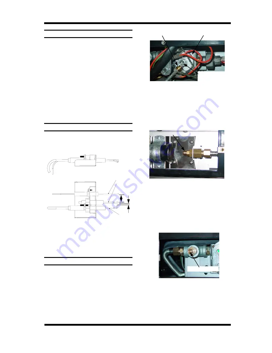
6.4.12 GAS TYPE CONVERSION
1) Remove side service panel to allow
access to gas control valve.
2) Unscrew and remove screw cap from
regulator incorporated in gas control.
3) Remove regulator spring from control.
Replace with correct spring supplied with
conversion kit.
LP Gas
- Blue Spring Colour
Natural Gas
- Green Spring Colour
4) Remove injector access panel from
bottom front of unit to allow servicing of
injector.
5) Unscrew and remove injector and
replace with appropriate item.
Natural Gas
ø 2.70 mm
LP Gas
ø 1.70 mm
Gas control valve
Enclosing screw cap
Figure 6.4.10
Regulator spring
screw cap
Injector
Figure 6.4.11
6) Connect gas and electrical supplies.
7) Operate oven and adjust regulator to
achieve correct pressure at pressure test
point (front RH corner).
Nat Gas 4.0” w.c. (1.00 kPa)
Nat Gas 4.5” w.c. (1.13 kPa) (110V only)
LP Gas 11.0” w.c. (2.75 kPa)
LP Gas 14.0” w.c. (3.50 kPa) (UK only)
Pressure test point
Figure 6.4.12
8) Conduct full leak test of the converted
oven prior to placing it into operation.
9) Refit
service
panels.