CHAPTER 2: INSTALLATION
MODEL 250DP DUAL PULSE
RESISTANCE WELDING POWER SUPPLY
990-280
2-9
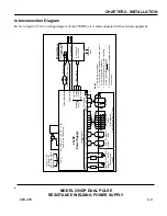
Figure 2-5. 250DP Equipment Interconnection Diagram
115
V AC, 1
5
A
50/6
0 Hz
, 1Ø
H
O
T
C
OM
GN
D
(B
LK
)(
WH
T
)(G
RN)
Pow
er
NO
CO
M
N
C
+
5
V
DC
CO
M
1
23
4
5
Fi
ri
ng
swi
tch
c
a
b
le
25
0DP
Powe
r S
uppl
y
DC
+
DC
AC
AC
IN B
G
ND
EMR
G
N
D
2
6
2
5
2
4
2
3
2
2
2
1
2
0
GN
D
L
V
1
L
V
2
C
OM
Co
ntrol s
ignals
Foo
tswi
tch
1
3
6
1
5
8
9
1
1
1
0
1
1
1
45
1
2
4321
1
1
2
3
4
1
Load
Load
5-5
0V DC
Rel
a
y 2
+
24-
115V D
C
Rel
a
y 1
AC
Us
er-s
upplied
pow
er
CH
G
Inhib
it
Eme
rgenc
y
Stop
2
6
2
5
2
4
2
3
2
2
2
1
2
0
Weld s
c
h
edule
sel
e
c
t
Us
er-s
upplied
Pro
gram
mable Lo
gic
C
ontrol
L1
L2
Initiate
Pow
er ou
tput
Air
v
a
lv
e
driv
er
24V AC
Re
turn
115
V AC
Auto
sens
e
1
2
3
4
1
2
1
Fir
in
g s
w
itc
h (
S
ee no
te 3)
(Se
e note
2)
Weld
c
ables
(Se
e note
1)
(Se
e note
4)
We
ld H
e
ad
Fo
rce firing
s
w
itch
(Se
e note
2)
Elec
trode
s
Air s
o
lenoid
24/1
15V AC
Pneu
matic
input
No
tes:
1.
Tie weld
c
ables
togethe
r.
2.
Fo
r non-
forc
e-fire
d oper
ation, s
hor
t pns
1 and 2
on t
he firing
s
w
itc
h c
o
nnec
tor.
3.
If an
optic
a
l firing s
w
itc
h
is
us
ed, th
e firing
s
w
itc
h c
onne
c
tion
is
n
o
t us
ed.
4.
Da
s
hed
lin
e
s
r
epres
ent air
ac
tu
ated w
e
ld hea
d
c
o
nnec
tions
.
Interconnection Diagram
Refer to figure 2-5 for a wiring diagram of the 250DP as it is interconnected with external equipment.

