CHAPTER 4: GETTING STARTED
MODEL 250DP DUAL PULSE
RESISTANCE WELDING POWER SUPPLY
4-4
990-280
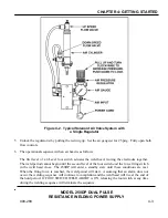
7 Adjust the upspeed flow control on the top of the cylinder so that the upper arm of the weld head moves
at a reasonable rate but does not slam against the up-stop. This adjustment is made by pressing, then
quickly releasing, the foot switch.
8 Adjust the regulator that controls the air pressure on the top of the cylinder to obtain the desired welding
force. Place the workpiece in position between the electrodes. Close the down speed flow control
located on the bottom of the cylinder.
9 Press the foot switch. Adjust the downspeed flow control so that the upper electrode moves at a
reasonable rate and does not impact the workpiece hard enough to damage either the electrode or the
workpiece. If the flow controls interact, readjust the air pressure which controls the pressure on the
bottom of the cylinder so that it is identical to that set on the other regulator. Then adjust the flow
control so that the upper electrode does not slam against the bottom electrode or the downstop.
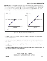
10 Adjust the pressure regulator, which controls the air pressure on the top of the air cylinder so that it is
just sufficient
to cause the Force Firing Switch in the head to close (see figure 4-3).
When the Force
Firing Switch in the head closes, the screen on the 250DP will no longer display
STANDBY. Re-adjust
both flow controls, as necessary.
Figure 4-3. Measuring Preset Firing Force of
the Weld Head with a Force Gauge


