MPI <4G63>
ï
On-vehicle Service
13D-103
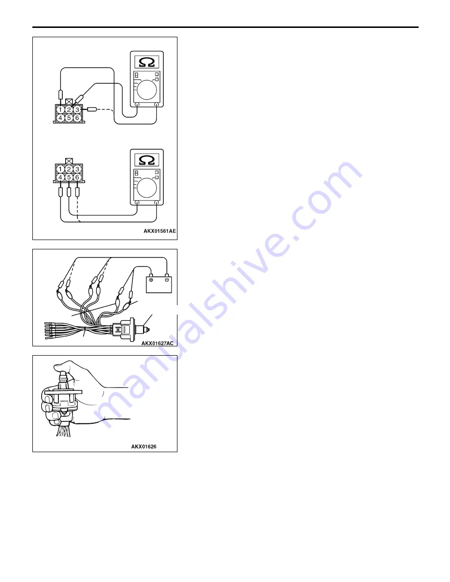
Check the Coil Resistance
1.
Disconnect the idle speed control servo connector.
2.
Measure the resistance between terminal No. 2 and either
terminal No. 1 or terminal No. 3 of the connector at the
idle speed control servo side.
Standard value: 28
ï
33
:
(at 20
_
C)
3.
Measure the resistance between terminal No. 5 and either
terminal No. 6 or terminal No. 4 of the connector at the
idle speed control servo side.
Standard value: 28
ï
33
:
(at 20
_
C)
4.
If the resistance deviates from the standard value greatly,
replace the idle speed control servo.
Operation Check
1.
Remove the throttle body.
2.
Remove the stepper motor.
3.
Connect the special tool Test harness (MB991709) to
the idle speed control servo connector.
4.
Connect the positive (+) terminal of a power supply
(approximately 6 V) to the terminals No. 2 and No. 5.
5.
With the idle speed control servo as shown in the
illustration, connect the negative (
ï
) terminal of the power
supply to each clip as described in the following steps,
and check whether or not a vibrating feeling (a feeling
of very slight vibration of the stepper motor) is generated
as a result of the activation of the stepper motor.
(1) Connect the negative (
ï
) terminal of the power supply
to the terminal No. 1 and terminal No. 4.
(2) Connect the negative (
ï
) terminal of the power supply
to the terminal No. 3 and terminal No. 4.
(3) Connect the negative (
ï
) terminal of the power supply
to the terminal No. 3 and terminal No. 6.
(4) Connect the negative (
ï
) terminal of the power supply
to the terminal No. 1 and terminal No. 6.
(5) Connect the negative (
ï
) terminal of the power supply
to the terminal No. 1 and terminal No. 4.
(6) Repeat the tests in sequence from (5) to (1).
6.
If vibration is detected during the test, the stepper motor
can be considered to be normal.
Terminal 5
Terminal 2
Iac motor
MB991709
Summary of Contents for Lancer 2005
Page 5: ...NOTES ...


