24
7 CiA 402 DRIVE PROFILE
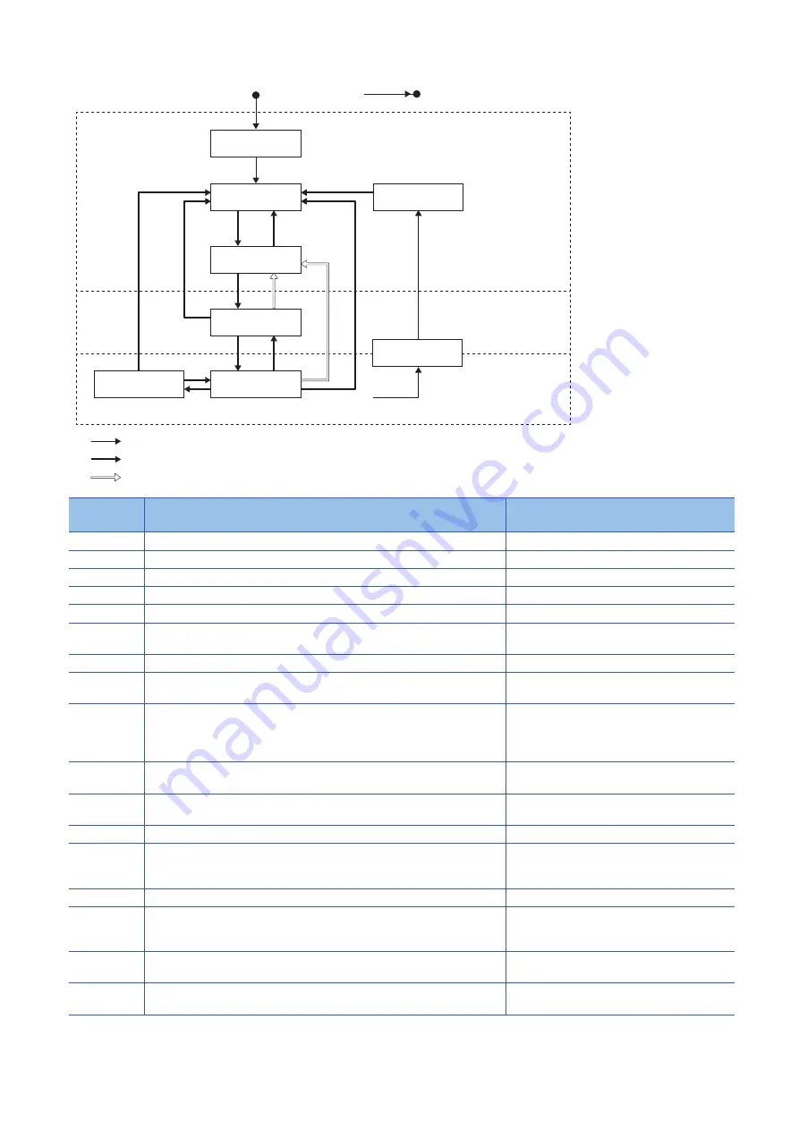
7.1 PDS state transitions
Transition
No.
Event
Description
(0)
Switching on control circuit power supply
Initialization
(1)
Automatic transition by switching on control circuit power supply
Communication setting
(2)
Transition by "Shutdown" command from master station
(3)
Transition by "Switch on" command from master station
The dynamic brake is released.
(4)
Transition by "Enable operation" command from master station
The operation becomes ready after servo-on.
(5)
• Transition by "Disable operation" command from master station
• Transition when RD (Ready) turned off
The operation is disabled after servo-off.
(6)
Transition by "Shutdown" command from master station
The dynamic brake operates.
(7)
Transition by "Disable Voltage" command or "Quick Stop" command from master
station
(8)
• Transition by "Shutdown" command from master station
• Transition by switching off main circuit power supply
• Transition after becoming servo-off (see the transition No. (5) if RD is turned off at
the same time)
The operation is disabled after servo-off and
dynamic braking.
(9)
Transition by "Disable Voltage" command from master station
The operation is disabled after servo-off and
dynamic braking.
(10)
Transition by "Disable Voltage" command or "Quick Stop" command from master
station
The dynamic brake operates.
(11)
Transition by "Quick Stop" command from master station
Initiation of Quick Stop
(12)
• Automatic transition after completion of "Quick Stop"
(When the value of "Quick stop" option code is 1, 2, 3, or 4)
• Transition by "Disable Voltage" command from master station
The operation is disabled after servo-off and
dynamic braking.
(13)
Alarm occurrence
The processing at the alarm occurrence is executed.
(14)
Automatic transition
After the completion of the processing for the alarm
occurrence, the operation is disabled by servo-off
and dynamic braking.
(15)
Transition by "Fault Reset" command from master station
An alarm reset is performed.
Resettable alarms are reset.
(16) (Not
supported)
Transition by "Enable Operation" command from master station
(When the Quick Stop option code is 5, 6, 7, or 8)
The operation becomes ready.
Not ready to
switch on
Switch on
disabled
Ready to
switch on
Switched on
Operation
enabled
Quick stop
active
(1)
(8)
(9)
(10)
(0)
Power off
Power on
(2)
(3)
(6)
(4)
(5)
(7)
(15)
Error occurs
(11)
(12)
(13)
Fault
Fault reaction
active
(14)
(B): Ready-on, Servo-off
Transition by slave
Transition by master
Transition by slave or master
(A): Ready-off, Servo-off
(C): Ready-on, Servo-on
(16)
Summary of Contents for MELSERVO-J5 MR-J5-G-N1
Page 2: ......
Page 24: ...22 6 SYNCHRONIZATION 6 2 Synchronous mode DC mode MEMO ...
Page 47: ...9 MANUFACTURER SPECIFIC FUNCTION 9 1 Torque limit selection 45 9 MEMO ...
Page 51: ......


