background image


-65- 

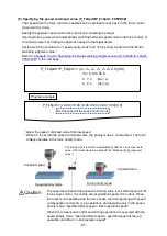
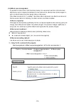
Practice 3: Specifying the force command value and the damping coefficient 

PStart 

Use the damping coefficient when the robot vibrates even the gain or force command value is 

adjusted in any method. 
Understand the effect of the damping coefficient through this practice. 

 Key learning points 


In this practice, the robot is vibrated on purpose to understand the effect of the 
damping coefficient. 
Normally, the damping coefficient is used when the robot does not stop vibrating 
even the gain is adjusted. 

Caution


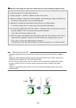
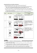
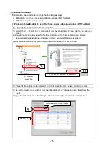
1) Execute program "3" to check the movement. 

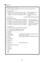
2) Create program "3" with RT ToolBox3 and write it to the robot. 

3) When the writing is completed, close the program. 

Open the program again, and check that the 8th line is "M_FsCod0=0" (tool coordinate system). 

4) Operate the robot by the JOG operation and move it to the PStart position. 

(* Teach the scale plate center position over the contact position again.) 

5) Turn OFF the enable switch of the T/B, switch to "Automatic" with the mode selection switch, 

and lower OVRD to 10%. Then execute the automatic operation. 

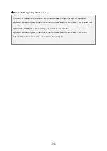
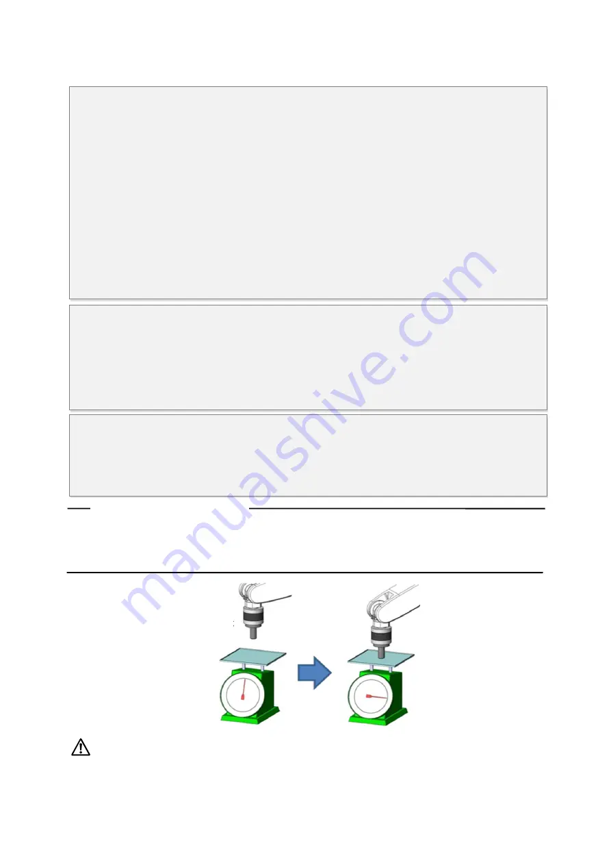
6) The robot stops for 10 seconds when the scale points at approximately 0.5 kg. Wait for the 

robot moving above and the servo turning OFF


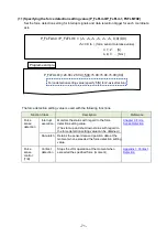
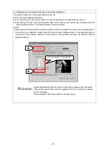
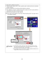
9) Input "0.05" to the Z-axis component in the 6th line P_FsDmp0 = 

(+0.00,+0.00,+0.00,+0.00,+0.00,+0.00) in the program. Then execute the automatic 
operation again.   

10) Check that the scale pointer settles at 0.5 kg. 

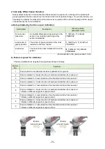
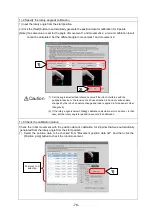
7) Open program "3", and adjust P_FsFCd0 = (+0.00,+0.00,+5.00,+0.00,+0.00,+0.00) in the 10th 

line, and change the Z-axis gain from "5" to between "40" and "50". Then execute the 
automatic operation again. 

8) Check that the needle of the scale points at 0.5 kg unstably.   

(If it is stable, adjust the gain within the range in which an error occurs.) 


Summary of Contents for MELFA BFP-A3614

Page 1: ...Mitsubishi Industrial Robot Robot Seminar Textbook Force Sensor Application BFP A3614 ...

Page 2: ......

Page 3: ...ing actual machine operation Force sensor parameter setting Connection and setting check Details of force sensor parameter 60 min 8 Force sense function interrupt processing Practice actual machine operation 9 Force sense Practice actual machine operation 75 min Lunch Lunch 5 Force sense function programming Details of control mode and control characteristics actual machine operation Force control...

Page 4: ...that teaching work is in progress on the start switch etc This also applies to maintenance work with the power source turned ON Indication of teaching work in progress DANGER Provide a fence or enclosure during operation to prevent contact of the operator and robot Installation of safety fence CAUTION Establish a set signaling method to the related operators for starting work and follow this metho...

Page 5: ... contact defects or wire breakage CAUTION Make sure that the workpiece weight including the hand does not exceed the rated load or tolerable torque Exceeding these values could lead to alarms or faults WARNING Securely install the hand and tool and securely grasp the workpiece Failure to observe this could lead to personal injuries or damage if the object comes off or flies off during operation WA...

Page 6: ...rty damage or bodily injury because the Handy GOT can automatically operate the robot regardless of whether the operation rights are enabled or not DANGER Do not connect the Handy GOT to a programmable controller when using an iQ Platform compatible product with the CR800 R controller Failure to observe this may result in property damage or bodily injury because the Handy GOT can automatically ope...

Page 7: ...after the wiring setup is completed CAUTION Use the network equipments personal computer USB hub LAN hub etc confirmed by manufacturer The thing unsuitable for the FA environment related with conformity temperature or noise exists in the equipments connected to USB When using network equipment measures against the noise such as measures against EMI and the addition of the ferrite core may be neces...

Page 8: ... Revision History Print Date Instruction Manual No Revision content 2018 07 31 BFP A3614 First print ...

Page 9: ...F 26 1 When turning the power ON 26 2 When turning the power OFF 26 Chapter 4 Parameter Setting 27 4 1 Force Sensor Parameter Setting 27 1 Force sensor parameter 27 2 Force control mode 28 3 Force control characteristics 29 4 2 Hand Parameter Setting 30 4 3 Connection and Setting Check 31 1 Checking the coordinate system 31 2 Display the force sensor data force sense monitor 34 4 4 Details of Forc...

Page 10: ...hanging the control characteristics 105 Practice 12 Changing the control characteristics 109 Chapter 9 Force Sense Detection 113 9 1 Force Sense Detection 113 9 2 Mo Trigger DefMoTrg SetMoTrg M_MoTrg 114 9 3 Force Detection Status M_FsLmtS P_FsLmtR 115 9 4 Data Latch P_FsLmtX P_FsLmtP P_FsLmtD 116 9 5 Data Verification P_FsMaxD P_FsCurD 117 9 6 Practice 119 Practice 13 Interrupt processing 119 Cha...

Page 11: ...ting 168 Appendix 5 2 RT ToolBox3 Creating a project for the oscillograph 169 Appendix 6 Reference Case 173 Appendix 6 1Program Example 173 1 Part Assembly Work Force Control 173 2 Phase Focusing Push 175 3 Coordinate calculation 177 Appendix 7 Parameter 181 Appendix 7 1 Setting Parameters and Status Variables for Force Sense Control Conditions 181 Appendix 8 Troubleshooting 187 Appendix 8 1 Behav...

Page 12: ...pieces 2 Robots can be operated while pushing in the desired direction with a fixed amount of force 3 Robot flexibility and contact detection conditions can be changed during movement 4 Contact status can be detected and interrupt processing performed 5 Position information and force information at the time of contact can be performed 6 Force data synchronized with position data can be saved as lo...

Page 13: ...face unit and robot controller Chapter 3 Device Connection and Wiring 3 1 Force Sense Interface Unit Robot Controller 7 Connect the force sense interface unit and force sensor Chapter 3 Device Connection and Wiring 3 2 Force Sense Interface Unit Force Sensor 8 Turn ON the force sense interface unit Turn ON the robot controller Chapter 3 Device Connection and Wiring 3 3 Power ON OFF 9 Set the force...

Page 14: ... 0 03 Consumption current mA 200 Output form RS422 Weight sensor unit g 360 580 External dimensions mm φ80 32 5 φ90 40 Protective structure IP30 1 When 1F FS001 W200 is used with RV 7 13 20FR RV 7 13 20F robot the moment beyond the moment rated load of the force sensor is applied if the tool workpiece of the robot s maximum load mass is grasped and its hand posture is set vertically to the install...

Page 15: ... 2 Force Sensor External Dimensions Outline drawings of the force sensor are shown below a 1F FS001 W200 Sensor detection center Tap hole for attachment 4 M6 1 0 Low head bolt for mounting sensor 4 M6 1 0 ...

Page 16: ...surface Pin hole for positioning 2 3H7 Pin hole for positioning 2 3H7 H7 effective depth 4 Detection axis Y Detection axis X connector Detection axis Z Tap hole for attachment 4 M6 1 0 Low head bolt for mounting sensor 4 M6 1 0 Sensor detection center H7 effective depth 4 ...

Page 17: ... 6 depth 5 4 M6 screw through hole at equidistant points on circumference 4 M3 screw depth 6 4 5 5 cut 10 through hole depth 10 at equidistant points on circumference sensor positioning pin hole Mechanical interface installing surface Force sensor installing surface depth 6 Section A A depth 5 4 M6 screw through hole bottom hole 4 9 at equidistant points on circumference 4 M3 screw depth 6 bottom ...

Page 18: ...e installing surface Force sensor installing surface depth 6 4 M6 screw through hole bottom hole 4 9 at equidistant points on circumference 4 M3 screw depth 6 bottom hole depth 11 depth 5 Section A A 4 7 cut 11 through hole depth 8 at equidistant points on circumference ...

Page 19: ...sense interface unit 3 Sensor attachment adapter 4 Adapter cable 5 24 VDC power supply 6 24 VDC power supply output cable 7 24 VDC power supply input cable 8 Serial cable between unit and sensor 9 SSCNET III cable 10 m 10 CD ROM Instruction Manual Sample Program 11 Force sensor attachment accessories 1 Force sensor 1F FS001 W1000 2 Force sense interface unit 3 Adapter cable 4 24 VDC power supply 5...

Page 20: ... sense interface unit 2F DQ561 Serial cable between unit and sensor 2F FSCBL1 05 Force sensor 1F FS001 W200 1F FS001 W1000 SSCNETIII cable 24 VDC input power supply cable 2F PWRCBL 02 24 VDC power supply 2F PWR 01 Machine cable Force sensor attachment example Robot controller Teaching box R56TB or R32TB RT ToolBox3 3F 14C WINE 3F 15C WINE RT ToolBox3 Pro 3F 16D WINE Computer ...

Page 21: ...e interface unit 2F TZ561 24 VDC output cable 2F PWRCBL 01 24 VDC power supply 2F PWR 01 24 VDC input power supply cable 2F PWRCBL 02 SSCNETIII cable Robot controller Machine cable Force sensor attachment example Teaching box R56 57TB or R32 33TB 3D 11C WINE 3D 12C WINE Force sensor Computer ...

Page 22: ...ecting micro force is needed Resolution smaller than below is needed Force Approx 0 15N 15 3gf Moment Approx 0 0046Nm 0 47gfm FR Series 4F FS002H W200 F Series 4F FS001 W200 FR Series 4F FS002H W1000 F Series 4F FS001 W1000 Select 4F FS002H W1000 or 4F FS001 W1000 Since the sensitivity decreases the micro force cannot be detected Select 4F FS002H W200 or 4F FS001 W200 Select 4F FS002H W200 or 4F F...

Page 23: ...ted 4F FS002H W200 Phase focusing Parts assembly Test Press withdraw Inset Deburr Polishing 4F FS002H W1000 4F FS002H W1000 F Series Application Robot RV F Series RH F Series RV 2F RV 4F RV 7F RV 13F RV 20F RH 3F RH 6F RH 12F RH 20F Close tolerance fit 4F FS001 W200 4F FS001 W1000 or 4F FS001 W200 Upward and downward limited 4F FS001 W200 Phase focusing Parts assembly Test Press withdraw Inset Deb...

Page 24: ...d force sensor coordinate origin Nm M W1 L1 g W2 L2 g F L3 g gravity acceleration m sec2 Depending on the hand shape the moment is applied when the hand weight or force is applied to the workpiece even the robot is facing downward Hand weight W1 kg Center of gravity of the hand Center of gravity of the Workpiece Workpiece W2 kg Reactive force F N ...

Page 25: ...sor center r Moment around force sensor coordinate origin Nm M W1 sinθ L1 g W2 sinθ L2 g g gravity acceleration m sec2 Moment is applied by the hand weight when the posture changes Center of gravity of hand Hand weight W1 kg Workpiece W2 kg Center of gravity of the Workpiece ...

Page 26: ...o define the relation between the force sensor coordinate system and robot coordinate system in the parameter setting 2 1 Attaching the Sensor Attachment Adapter Attach the sensor attachment adapter to the robot mechanical interface with the following method Mechanical interface Attaching method of the sensor attachment adapter Mechanical interface Sensor attachment adapter 3 pin Hexagon socket he...

Page 27: ...sure even contact between the sensor installation surface and sensor attachment adapter Figure 1 to 4 below Note that the sensor may be damaged if any of the bolts are overly tightened at once Always tighten each bolt a little at a time until the recommended torque value is reached See below Force sensor Tightening torque Nm 1F FS001 W200 6 1F FS001 W1000 10 Tighten each bolt in diagonal orders gr...

Page 28: ...x the cable with the cable tie and cable tie mount so that bend radius of the force sensor cable becomes 25 mm or more Ensure that the force sensor cable and connector are not subject to bending forces Force sensor cable Force sensor Sensor attachment adapter Cable tie fixture Force sensor Bend radius 25 mm or more Sensor attachment adapter Cable tie Cable tie fixture Note for cable wiring If the ...

Page 29: ...0 0 0 20 A Note 1 Force sensor coordinate system home position sensor detection center Mechanical interface Mechanical interface Force sensor coordinate system home position sensor detection center X and Y direction position of the mechanical interface and force sensor detection center match Installation position X Y mm 0 mm Installation position Z mm A H mm Sensor attachment adapter A mm Sensor d...

Page 30: ...lation angle is as follows Force sensor Installation angle FSXTL deg A X axis rotation B Y axis rotation C Z axis rotation 1F FS001 W200 0 180 0 1F FS001 W1000 0 180 0 Mechanical interface coordinate system Rotation angle of the force sensor coordinate system for the mechanical interface Y axis rotation direction B deg 180 deg Parameter installation angle FSXTL Xm Ym Zm FXs FZs FYs Force sensor co...

Page 31: ...e sensor movable parts Caution There are some hands equipped with air supply cables and or power supply cables Attaching them to the tool side of the force sensor will cause the cables to be swung resulting in generation of a centrifugal force which may adversely affect the accuracy of obtained force data The accuracy of the data may also be affected by the weight of the cables Take appropriate me...

Page 32: ... 21 Chapter 3 Device Connection and Wiring 3 1 Force Sense Interface Unit Robot Controller Connect the force interface unit and robot controller 1 FR series a CR800 D controller CR800 D controller front ...

Page 33: ... 22 b CR800 R controller CN1 connector CR800 R controller front To OPT1 connector CPU module SSCNET III cable ...

Page 34: ... 23 2 F series a CR750 D controller ...

Page 35: ... 24 b CR751 D controller ...

Page 36: ... 25 c CR750 Q CR751 Q controller CPU module ...

Page 37: ...g the power ON Turn ON the power to the force sense interface unit followed by the robot controller 2 When turning the power OFF Turn OFF the power to the robot controller followed by the force sense interface unit There is no need to turn OFF the force sense interface unit power if only the controller is ON Caution Do not disconnect the SSCNET III cable after turning ON the power Furthermore do n...

Page 38: ...1 Robot arm 2 Axis AXJNO 9 9 Axis 9 of the robot 3 Place mm FSXTL X 0 Distance between the mechanical interface coordinate system and force sensor detection position Y 0 Z 32 4 Angle deg FSXTL A 0 Rotation angle of the force sensor coordinate system for the mechanical interface coordinate system B 180 C 0 5 Max Offset FSCORMX Position 200 A value to limit the travel distance from the position wher...

Page 39: ... A B C L1 L2 Position 4 Stiffness coefficient FSSTF01 X Y Z A B C 0 10 Setting value for axis flexibility stiffness coefficient The higher the value is the stiffer the axis is L1 L2 0 5 Damping coefficient FSDMP01 X Y Z A B C L1 L2 0 Setting of the axis response characteristics damping coefficient Adjust this when the robot vibrates at contact Force Control Mode parameter setting window 3 Control ...

Page 40: ... X Y Z 2000 Used for the force sense detection and contact detection function A B C 200 5 Mode Switch Judgment FSSWF01 X Y Z A B C L1 L2 0 Setting for switching judgment value of the speed force control mode Valid when the speed command value is set 6 Speed Command FSSPD01 X Y Z A B C L1 L2 0 Specify the movement speed at no contact in force control speed priority mode Force Control Characteristic...

Page 41: ...ter of gravity position from the mechanical interface coordinate system when setting it Attachment adapter Force sensor X Y Z Mechanical interface coordinate system Zm Ym Xm Hand Weight and size parameter setting window Setting example Size of hand X 150 mm Y 20 mm Z 150 mm Attachment adapter Z 16 mm Force sensor Z 32 5 mm Center of gravity position of hand X 75 mm Y 0 mm Z 100 mm Total weight han...

Page 42: ...ristics to 1 Select the number of control mode and control characteristics set in Chapter4 4 1 Force Sensor Parameter Setting 3 Turn ON the servo and enable the force sense control 4 Push the tool tip of the robot in any direction by finger Check if the robot follows it and moves in that direction If the coordinate system is set correctly the robot follows it 5 If the robot does not follow check t...

Page 43: ...he FORCE screen 3 Force screen First enable the offset cancel Push the F3 key in the FORCE screen When the offset cancel confirmation screen is displayed press the F1 key Yes For the offset cancel refer to Chapter5 5 4 12 Offset cancel designation 4 Force screen Next specify the number for CONTROL MODE and CONTROL FEATURE Press the F2 key PARAM in the FORCE screen 5 Force Parameter screen Specify ...

Page 44: ...s the SERVO button to turn ON the servo The control mode is set to 1 and control feature to 1 as an example 7 Force screen Press the F1 key in the FORCE screen to enable the force sense control FORCE ON Press the F1 key to enable disable ON OFF the force sense control Switch using the F1 key ...

Page 45: ...nnection and settings again a Display current value of the force sensor on teaching box Step How to operate T B screen Description of the operation method 1 JOG operation screen Press the JOG key to display the JOG operation screen 2 JOG operation screen Press the FUNCTION key and display FORCE as the function menu at the bottom of the screen Press the F3 key FORCE and display the FORCE screen 3 F...

Page 46: ...rizontal multi joint robots FSHAND 1 integer 0 Force sensor tolerance FSLMTMX 6 real number Sets the tolerance value of the force sensor Refer to Chapter4 4 4 4 Tolerance value FSLMTMX 0 0 0 0 0 0 0 0 0 0 0 0 Force sense control offset limit FSCORMX 2 real number Sets the maximum position offset by the force sense control Refer to Chapter4 4 4 3 Maximum offset value FSCORMX 10 0 10 0 Force sensor ...

Page 47: ...Enter a mechanical number corresponding to the servo control axis number being used Always set 0 for axes that are not being used If using force sense interface unit Servo control axis No Set 1 for axis No 1 0 0 0 0 0 0 0 0 0 0 0 0 0 0 0 0 If not using additional axis functions Set these parameters as follows if not using the additional axis functions AXJNO 9 0 0 0 0 0 0 0 0 0 0 0 0 0 0 0 AXMENO 1...

Page 48: ... Z axis deg 0 0 0 0 0 0 0 0 180 0 0 0 vertical multi joint robots 0 0 0 0 0 0 0 0 0 0 180 0 horizontal multi joint robots b Force sense hand coordinate system FSHAND Parameter Parameter Name No of Elements Description Factory Default Setting Force sensor coordinate system selection FSHAND 1 integer Selects the force sensor coordinate system hand system left hand system right hand system The force ...

Page 49: ... in which the opposite force is applied when the robot moves to the positive direction in the mechanical interface coordinate system The home position of the coordinate system overlaps the mechanical interface coordinate system The sign of force sense coordinate system is the reversed sign of the mechanical interface coordinate system Force sense coordinate system mechanical interface Mechanical i...

Page 50: ... sensor coordinate system home position viewed from the mechanical interface coordinate system is 0 0 32 FSXTL is set as follow FSXTL 1st element 0 FSXTL 2nd element 0 FSXTL 3rd element 32 Rotational transfer To align the posture of the force sense coordinate system mechanical interface and force sensor coordinate system it is sufficient to rotate 180 degrees around the Ym axis and FSXTl is set as...

Page 51: ...from the mechanical interface coordinate system is 0 0 50 and therefore the FSXTL settings are as follows FSXTL 1st element 0 FSXTL 2nd element 0 FSXTL 3rd element 50 Rotational transfer To align the posture of the force sense coordinate system mechanical interface and force sensor coordinate system it is sufficient to rotate 180 degrees around the Ym axis after rotating 30 degrees around the Zm a...

Page 52: ...e sensor data Fy tolerance N 3rd element Force sensor data Fz tolerance N 4th element Force sensor data Mx tolerance N m 5th element Force sensor data My tolerance N m 6th element Force sensor data Mz tolerance N m 0 0 0 0 0 0 0 0 0 0 0 0 Set the minimum required tolerance for the work being performed within the force sensor rated value Refer to section Chapter1 1 1 Force Sensor Specifications for...

Page 53: ...NCTL The minimum control force of force sensor can be changed Even if the force sensor does not touch the workpiece etc during force sense control the robot may vibrate due to stationary noise of sensor data In this case increasing the minimum control force solves the problem However increasing the minimum control force widens the dead zone Therefore the sensitivity of the force sense detection fo...

Page 54: ...ange Changes control characteristics during robot movement Changes control characteristics in the trigger conditions Gravity offset cancel Performs offset cancel in response to a change in the direction of gravity applied to the force sensor by hand load at the time of posture change Force sense detection Interrupt execution Detects contact status and performs interrupt processing Defines interrup...

Page 55: ... the force applied on the workpiece when performing insertion work Furthermore the robot position is offset while following the assembly part shape allowing teaching position displacements to be absorbed In the stiffness control the reactive force will increase in proportion to displacement If the reaction force is too large please set the limit value for the reactive force using the limited stiff...

Page 56: ...e command FscOn Enable the force sense control function using the force sensor in a program For details refer to Chapter5 5 3 Condition Groups and Condition Numbers Control mode Specify the control mode number for force sense control Setting range 1 to 9 Control characteristics Specify the control characteristics number for force sense control Setting range 1 to 9 Offset cancel designation Specify...

Page 57: ... the ON OFF button The enabled disabled status is displayed on the T B screen Step How to operate T B screen Description of the operation method 1 JOG operation screen Press the JOG key to display the JOG operation screen 2 JOG operation screen Press the FUNCTION key and display FORCE as the function menu at the bottom of the screen Press the F3 key FORCE and display the FORCE screen 3 Force scree...

Page 58: ...ing coefficient P_FsDmp1 P_FsDmp0 FSDMP01 FSDMP0 Force sensor bias value P_FsBias1 P_FsBias0 FSBIAS01 FSBIAS0 Load center of gravity position P_FsGrPos1 P_FsGrPos0 FSGRP01 FSGRP0 Load mass M_FsMass1 M_FsMass0 FSMASS01 FSMASS0 corresponds to group Nos 2 to 9 Condition group Control characteristics corresponds to group Nos 2 to 9 Setting Item Condition Numbers 1 0 1 2 9 Force command value limit val...

Page 59: ...control mode P_FsSwF0 0 00 0 00 0 00 0 00 0 00 0 00 0 0 Set the force speed judgment value Control characteristics 1 P_FsGn1 0 00 0 00 4 00 0 00 0 00 0 00 0 0 Force control gain µm N P_FsFLm1 0 00 0 00 0 00 0 00 0 00 0 00 0 0 Force detection setting value N P_FsFCd1 0 00 0 00 12 00 0 00 0 00 0 00 0 0 Force command P_FsSpd1 0 00 0 00 0 00 0 00 0 00 0 00 0 0 Set the speed of the speed control mode P...

Page 60: ... Mvs P1 3 Dly 0 5 Input Dly before the offset cancel Fsc On 9 4 1 Enable the force sense control with control mode 9 control characteristics 4 and offset cancel enabled operates with the control mode 9 control characteristics 4 set in the parameter Insert complete conditions are input interrupt IF condition statement and others Fsc Off Disable the force sense control End Control characteristics Co...

Page 61: ...of the Teaching Box R56TB 3 Selecting the Control Mode Control characteristics Step How to operate T B screen Description of the operation method 1 JOG operation screen Press the FUNCTION key and display FORCE as the function menu at the bottom of the screen Press the F3 key FORCE to display the FORCE screen 2 Force screen Press the F2 key PARAM 3 Force condition screen Specify the numbers for CON...

Page 62: ...l 4 Specifying the force control mode Stiffness coefficient Sets the flexibility for axes for which stiffness control limited stiffness control is selected 6 Specifying the stiffness coefficient Damping coefficient Sets the responsiveness for axes for which force control or stiffness control limited stiffness control is selected Adjust when the robot vibrates at contact 7 Specifying the damping co...

Page 63: ... contact etc 9 Specifying the speed command value Mode switching judgment value Sets the speed force control mode switching judgment value This is valid only when a speed command value has been set 10 Specifying the mode switch judgment value Force sense control gain Sets the response sensitivity for axes for which force control limited stiffness control or stiffness control is selected Adjustment...

Page 64: ... necessary Setting item Status variable 0 1 Parameter 1 to 9 Force control mode Position control Force control Stiffness control Limited stiffness control Control mode Force sense control coordinate system M_FsCod FSCOD0 Force sense control mode P_FsMod FSFMD0 Stiffness coefficient P_FsStf FSSTF0 Damping coefficient P_FsDmp FSDMP0 Force sensor bias value P_FsBias FSBIAS0 Load center of gravity pos...

Page 65: ...ense control coordinate system to Tool coordinate system Program example M_FsCod0 0 Force sense coordinate system tool Tool hand coordinate system Force sense coordinate system tool Force sense coordinate system XYZ Robot coordinate system Force sense coordinate system XYZ coordinate system The reversed direction of the tool hand coordinate system is the direction of the coordinate axis The home p...

Page 66: ...ection are set with the Force command value Specify with P_FsFCd0 P_FsFCd1 Force pressing Grinding work c Stiffness Control Mode Limited stiffness control Control method Application Decreases the stiffness of the specified axis Flexibility is set with the Stiffness coefficient The limit value for the limited stiffness control is set with the limit value Fitting insertion work Following teaching wo...

Page 67: ...played on the GOT changes to the side 7 When the servo of the robot is turned OFF set M_FsCod0 1 of program 1 with RT ToolBox3 again and write the program to the robot 8 After OVRD is lowered to 10 execute the automatic operation The force sensor is enabled for 60 seconds in the program When the force in upper direction is applied to the tip of the hand check that the Z axis data displayed on the ...

Page 68: ...ction setting value N 12 P_FsFCd0 0 00 0 00 0 00 0 00 0 00 0 00 0 0 Force command 13 P_FsSpd0 0 00 0 00 0 00 0 00 0 00 0 00 0 0 Set speed control mode speed 14 P_FsSwF0 0 00 0 00 0 00 0 00 0 00 0 00 0 0 Set force speed judgment value 15 Force control 16 PStart 235 00 0 00 220 00 180 00 0 00 180 00 7 0 17 Move the robot to PStart position in advance 18 Tool 0 00 0 00 185 00 0 00 0 00 0 00 19 Loadse...

Page 69: ...n be obtained In the following image stiffness control is performed only for the tool Z axis By setting 0 5 N mm for the Z direction stiffness coefficient and the teaching position at 5 mm below the contact surface force F produced on the contact surface is calculated as follows The smaller the stiffness coefficient the smaller the reactive force helping to deal with greater displacements When 0 0...

Page 70: ... the hand check that the robot returns to the original position when the hand is released 7 When the servo of the robot is turned OFF change the XYZ component of P_FsStf0 in the 5th line of program 2 from 0 1 to 0 5 with RT ToolBox3 again and save it Then execute the automatic operation 8 As step 6 check the difference of stiffness when the force is applied to the tip of the robot and the differen...

Page 71: ...FsFCd0 0 00 0 00 0 00 0 00 0 00 0 00 0 0 Force command 13 P_FsSpd0 0 00 0 00 0 00 0 00 0 00 0 00 0 0 Set speed control mode speed 14 P_FsSwF0 0 00 0 00 0 00 0 00 0 00 0 00 0 0 Set force speed judgment value 15 Stiffness control 16 PStart 235 00 0 00 220 00 180 00 0 00 180 00 7 0 17 Move the robot to PStart position in advance 18 Tool 0 00 0 00 185 00 0 00 0 00 0 00 19 Loadset 1 1 20 OAdl On 21 Spd...

Page 72: ...er the value the greater the effect in suppressing vibrations however positional offsetting is delayed with sudden changes in force resulting in a greater force applied the moment contact is made with the workpiece Adjust the damping coefficient after adjusting the force sense control gain Vibrations also occur if the force sense control gain is too great P_FsDmp0 P_FsDmp1 0 0 0 0 0 0 to 1 0 X Y Z...

Page 73: ...ess control is enabled the robot moves to a position at which the reactive force corresponding to the displacement and stiffness coefficient can be obtained In the normal stiffness control when the stiffness coefficient or displacement is increased the reactive force becomes large On the other hand in the limited stiffness control the force is automatically controlled so that the reactive force do...

Page 74: ...t low speed by JOG operation in the axis direction for which force sense control force control stiffness control limited stiffness control is enabled until contact is made with the target object speed override approx 5 3 If the robot rebounds in the opposite direction from the movement direction when contact is made it is necessary to lower the gain setting value The gain setting value can be incr...

Page 75: ... 64 MEMO Please use this page for your memo ...

Page 76: ...4 Operate the robot by the JOG operation and move it to the PStart position Teach the scale plate center position over the contact position again 5 Turn OFF the enable switch of the T B switch to Automatic with the mode selection switch and lower OVRD to 10 Then execute the automatic operation 6 The robot stops for 10 seconds when the scale points at approximately 0 5 kg Wait for the robot moving ...

Page 77: ... 00 0 00 4 90 0 00 0 00 0 00 0 0 Force command 13 P_FsSpd0 0 00 0 00 0 00 0 00 0 00 0 00 0 0 Set speed control mode speed 14 P_FsSwF0 0 00 0 00 0 00 0 00 0 00 0 00 0 0 Set force speed judgment value 15 Control 16 Reference PStart 17 PStart 60 00 250 00 290 00 180 00 0 00 90 00 7 0 18 Move the robot to PStart position in advance 19 Tool 0 00 0 00 185 00 0 00 0 00 0 00 20 Loadset 1 1 21 OAdl On 22 S...

Page 78: ... The robot always operates in the force priority mode The priority mode is switched automatically based on the sensor data value The threshold value is set with the Mode switching judgment value Constant speed Constant force Force priority mode Speed priority mode P_FsSpd0 P_FsSpd1 0 0 0 0 0 0 to 50 0 X Y Z mm s A B C deg s P_FsSpd0 0 00 10 00 0 00 0 00 0 00 0 00 0 0 Set the speed of the speed con...

Page 79: ... value or below Speed priority mode The robot is controlled so that the speed specified with the speed command value is reached The robot moves in the direction which satisfies the force specification value by following the axis direction for which force control is specified P_FsSwf0 P_FsSwf1 0 0 0 0 force sensor tolerance value to force sensor tolerance value X Y Z N A B C N m P_FsFCd0 0 0 1 0 0 ...

Page 80: ...6 When the program has stopped open the program again with RT3 and input 20 to the Z component of P_FsSpd0 0 00 0 00 0 00 0 00 0 00 0 00 0 0 in the 13th line Then write 0 5 to the Z component of P_FsSwF0 0 00 0 00 0 00 0 00 0 00 0 00 0 0 in 14th line and write it to the robot controller Understand the speed priority mode and force priority mode using the mode switching judgment value Experience sh...

Page 81: ...sFCd0 0 00 0 00 5 00 0 00 0 00 0 00 0 0 Force command 13 P_FsSpd0 0 00 0 00 0 00 0 00 0 00 0 00 0 0 Set speed control mode speed 14 P_FsSwF0 0 00 0 00 0 00 0 00 0 00 0 00 0 0 Set force speed judgment value 15 Control 16 PStart 60 00 250 00 350 00 180 00 0 00 90 00 7 0 17 Move the robot to PStart position in advance 18 Tool 0 00 0 00 185 00 0 00 0 00 0 00 19 Loadset 1 1 20 OAdl On 21 Spd M_NSpd Set...

Page 82: ...ue The start up and shut down status with regard to the force detection setting value can be obtained Chapter 9 Force Sense Detection Data latch Retains the sensor data and position data at the moment when exceeded the force detection setting value Force sense control T B Contact detection Stops the JOG operation at the moment when exceeded the specified force moment Appendix 3 Contact Detection P...

Page 83: ...n If the posture changes significantly in every work it is necessary to perform offset cancel again after the posture changes Offset cancel conditions Always satisfy the following conditions when performing offset cancel Robot at complete stop No contact with hand workpiece etc no external force applied Offset cancel setting method The offset cancel is set in the following two methods 1 Using Fsc ...

Page 84: ...een Press the JOG key to display the JOG operation screen 2 JOG operation screen Press the FUNCTION key and display FORCE as the function menu at the bottom of the screen Press the F3 key FORCE and display the FORCE screen 3 Force screen Push the F3 key in the FORCE screen When the offset cancel confirmation screen is displayed press the F1 key Yes Pick Up The offset cancel status is reset by rest...

Page 85: ...operation 2 Switch the teaching box to the force screen to check that the value of Mx to Mz is other than 0 3 Press the OFFSET in the teaching box and then press YES 4 Switch the teaching box to the force screen to check that the value of Mx to Mz is 0 0 Due to the noise and error the value will not be exactly 0 ...

Page 86: ... FSMASS0 corresponds to the group number 1 to 8 b Posture required for calibration The force calibration is required nine postures shown in below Posture No Condition 1 Posture that the mechanical interface is parallel to the ground 2 Posture rotated in X axis direction of mechanical interface from posture 1 3 Posture rotated in X axis direction of mechanical interface from posture 1 4 Posture rot...

Page 87: ...the program name for the force calibration in the force calibration start screen Input program is generated automatically and force sensor calibration is executed Note After calibration is complete the program will be deleted from the controller 1 2 Specify the control mode number 1 to 9 that stores the force sensor calibration result 1 Select the control mode number from the drop down list of Sto...

Page 88: ...art position Note Set the position at which the mechanical interface of robot is parallel to the ground to the start position The force sense calibration rotates around the mechanical interface twice in the specified angle in X axis and Y axis rotation Adjust the start position to the position that does not interfere with the peripheral device 2 Current position Start position 4 If Auto adjustment...

Page 89: ... 9 points that was automatically generated from the rotary angle from the start position 1 Select the position data to be checked from Movement position data list and then click the Position jump button to check the robot movement 1 2 1 Set the angle smaller than reference value if the robot interferes with the peripheral device or the tension of air hose attached to hand of various cable changes ...

Page 90: ...4 Please click Finish button and end the calibration Note If the force sensor calibration is finished by clicking the Finish button the program used in the calibration is deleted 1 2 3 4 Hand weight Center of the gravity position of hand 1 If Start button is clicked robot moves Please check the safety of around the robot If the override is greater than 10 override is changed to 10 for safety Pleas...

Page 91: ...ent position and the force sensor data required to the force calibration Estimate the hand load by executing the following program Program example 1 Force sense calibration execution 2 Dim PP 9 3 Servo On 4 Mov PP 1 Robot moves to the start point 5 Dly 1 6 FsHndEst On 0 Execute the calibration 7 For M1 1 To 9 Step 1 8 Mov PP M1 Robot moves to the calibration posture 9 Dly 1 5 Wait until the robot ...

Page 92: ...s and B axis to the positive and negative direction gradually approximately 20 to 45 degrees against the reference position 3 Execute automatic operation and check that P_FsBias0 P_FsGrPos0 M_FsMass0 are changed after the program has stopped Calibration posture movement image Posture 1 Posture 2 X axis rotation Y axis rotation Posture 3 Posture 5 Posture 4 Posture 1 When teaching PP 2 to PP 9 set ...

Page 93: ...00 0 00 0 00 0 0 Force detection setting value N 12 P_FsFCd0 0 00 0 00 5 00 0 00 0 00 0 00 0 0 Force command 13 P_FsSpd0 0 00 0 00 30 00 0 00 0 00 0 00 0 0 Set speed control mode speed 14 P_FsSwF0 0 00 0 00 0 00 0 00 0 00 0 00 0 0 Set force speed judgment value 15 Control 16 Tool 0 00 0 00 185 00 0 00 0 00 0 00 17 PBias0 P_FsBias0 Bias value with control mode 0 18 PGrav0 P_FsGrPos0 Center of gravi...

Page 94: ...7 37 0 00 233 46 180 00 0 00 180 00 7 0 PP 2 327 37 0 00 233 46 160 21 0 00 180 00 7 0 PP 3 327 37 0 00 233 46 160 15 0 00 180 00 7 0 PP 4 327 37 0 00 233 46 180 00 20 90 180 00 7 0 PP 5 327 37 0 00 233 46 180 00 20 00 180 00 7 0 PP 6 327 37 0 00 233 46 150 00 0 00 180 00 7 0 PP 7 327 37 0 00 233 46 150 00 0 00 180 00 7 0 PP 8 327 37 0 00 233 46 180 00 30 00 180 00 7 0 PP 9 327 37 0 00 233 46 180 ...

Page 95: ... 84 MEMO Please use this page for your memo ...

Page 96: ...r Parameter Name No of Elements Description Default Factory Setting Log function FSLOGFN 3 integers Specifies settings for the force sense log function 1st element Enables disabled the log function Setting range 0 disable 1 enable 2nd element Selects the collected force sensor data type Setting range 0 Raw data with offset cancel 1 Raw data without offset cancel 2 Data after coordinate conversion ...

Page 97: ...xecuted a log file with specified file No name is generated a Start acquiring log data Starts force sensor data and position command position FB and current FB value logging b End acquiring log data Ends force sensor data and position command position FB and current FB value logging Log File No Specifies the log file No containing collected data Setting range 1 to 999999999 FsLog On FsLog Off Log ...

Page 98: ...to 10 Then execute the automatic operation 6 When the automatic operation starts the log is acquired for 20 seconds followed by the external force and save it as 999 7 Turn OFF the servo and check that the automatic operation program has stopped Then check the log with RT3 Select Force Control Log File Viewer in Tool of RT ToolBox3 and then select 999 from the robot controller Understand the force...

Page 99: ...etection setting value N 12 P_FsFCd0 0 00 0 00 0 00 0 00 0 00 0 00 0 0 Force command 13 P_FsSpd0 0 00 0 00 0 00 0 00 0 00 0 00 0 0 Set speed control mode speed 14 P_FsSwF0 0 00 0 00 0 00 0 00 0 00 0 00 0 0 Set force speed judgment value 15 Control 16 Tool 0 00 0 00 185 00 0 00 0 00 0 00 17 GoSub INIT 18 Main 19 FsLog On 20 Fsc On 0 0 1 Start force sense control 21 Dly 15 22 Fsc Off 23 FsLog Off 99...

Page 100: ...g file saved in the R C robot controller to personal computer 2 Copy file check box When this is selected and the force log file is read with the Read in RC button the save force log window appears after the reading completes and the force log file can be saved to the personal computer 3 Select File Read the log file selected in the log file list 4 Select Data Select the data to display in graph 5...

Page 101: ...troller can be transferred to the FTP server personal computer by using FsOutLog command of robot language MELFA BASIC The transferred data can be used for checking the work quality and analyzing at error occurrence For details refer to Appendix 5 Force Sense Log File FTP Transfer ...

Page 102: ...ix 5 2 RT ToolBox3 Creating a project for the oscillograph 1 Select Oscillograph in Tool from the project tree 2 Open the communication setting window and select Real time monitor for Method When using the real time monitor use Ethernet for communicating the personal computer and robot Note 1 3 Select Force sensor from the list in Select the request data 4 The oscillograph is displayed The force i...

Page 103: ... 92 MEMO Please use this page for your memo ...

Page 104: ...obot moves based on this command By performing teaching operation teaching operation from T B or current position reading from RT ToolBox3 from the teaching box or RT ToolBox3 while force control is enabled the position command 1 is taught and a position different from the actual robot position 2 is taught When teaching the position offset by the force sense control perform teaching position searc...

Page 105: ...displayed on the teaching box will be taught to the position variables add the offset amount by the force sense control before teaching Refer to Chapter7 7 1 Teaching Position Precautions in the previous page By executing this function the position displayed on the teaching box can be replaced with the actual position with force sense control enabled Even this function is not executed and the forc...

Page 106: ...n is displayed Press the F1 key Yes and execute the teaching position search function 6 FORCE screen When the position search is completed the screen returns to the FORCE screen 7 JOG operation screen Press the F4 key JOG to return to the JOG operation screen 8 Position editing window Press the JOG button release JOG mode and display the POS screen 9 JOG operation screen Press the F2 key Teach For...

Page 107: ...ins while following the workpiece shape with stiffness control stiffness coefficient 0 external force acts on one side of the pin By performing teaching position search at such times the robot can be moved in a direction in which no external force acts There may be cases in which the robot is unable to move to a position in which no external force acts by performing this function only once In such...

Page 108: ...me and move it to the position where the scale pointer points at 2 kg by JOG operation and record the value of Z 2 Input the recorded Z value to PTRG Z in the 20th line 3 Execute program 8 4 Check P1 to P5 by the program monitor 5 Check that P_Curr is changed despite the position during the force sense control and after the force sense control are the same 2kg Set the Z component of PTRG 20 PTRG Z...

Page 109: ...d0 0 00 0 00 5 00 0 00 0 00 0 00 0 0 Force command 13 P_FsSpd0 0 00 0 00 0 00 0 00 0 00 0 00 0 0 Set speed control mode speed 14 P_FsSwF0 0 00 0 00 0 00 0 00 0 00 0 00 0 0 Set force speed judgment value 15 Control 16 Tool 0 00 0 00 185 00 0 00 0 00 0 00 17 GoSub INIT 18 Main 19 PTRG P_Fbc 20 PTRG Z 260 21 Ovrd 5 22 Fsc On 0 0 1 Start force sense control 23 Mvs PTRG 24 Dly 5 25 P1 P_Cur Position co...

Page 110: ...Center of gravity position of hand tip with control mode 0 42 M_FsMass0 0 Hand tip weight with control mode 0 43 Loadset 1 1 44 OAdl On 45 Servo On 46 Wait M_Svo 1 47 Pnow P_Fbc 48 If Pnow Z PHome Z Then 49 Pnow Z PHome Z 50 Mvs Pnow 51 Pnow2 Align Pnow 52 Mvs Pnow2 53 Dly 0 2 54 EndIf 55 Mov PHome 56 Dly 0 2 57 Return 58 ...

Page 111: ... 100 MEMO Please use this page for your memo ...

Page 112: ...o Tool Coordinate System 4 Open the Force Control Characteristics 2 window and select the Speed condition tab Then set all the values to 0 5 Select the Force condition tab in the Force Control Characteristics 2 window 6 Set Force Gain to 5 00 for X Y Z A B and C 7 Set the Z axis of Force Cmd to 5 00 8 Set Force detection to 2000 for X Y and Z 200 for A B and C Then press the Write button 9 Open th...

Page 113: ...t Coordinate system to Tool Coordinate System 4 Open the Force Control Characteristics 2 window and select the Speed condition tab Then set all the values to 0 5 Select the Force condition tab in the Force Control Characteristics 2 window 6 Set Force Gain to 5 00 for X Y and Z 10 00 for A B and C 7 Set the Z axis of Force Cmd to 5 00 8 Set Force detection to 2000 for X Y and Z 200 for A B and C Th...

Page 114: ... position at which the change to the control characteristics setting is started Specify with a percentage for the next interpolation start point end point Setting range 0 to 100 Change time Specifies the time taken to change the control characteristics setting The mode switching judgment value and force detection setting value changes immediately regardless of this setting Setting range 1 to 1000 ...

Page 115: ...th a constant Setting range 0 to 60 s If omitted timeout processing is not performed Execution method Specifies the timeout monitoring execution method for this command with a constant 0 Proceeds to next program without waiting for Mo trigger ON 1 Does not proceed to next program until Mo trigger turns ON or timeout reached Error specification Specifies whether an error occurs following a timeout ...

Page 116: ...imately 10 mm above the scale for P1 For P1 teach the position close to the robot rather than the center of the scale 3 When the program is executed the robot moves in the Y direction Check that the pushing force changes from the last half of the movement 4 Also check how the force changes by changing the argument of FsGChg ...

Page 117: ... 13 P_FsSpd0 0 00 0 00 0 00 0 00 0 00 0 00 0 0 Set speed control mode speed 14 P_FsSwF0 0 00 0 00 0 00 0 00 0 00 0 00 0 0 Set force speed judgment value 15 Control characteristics 1 16 P_FsGn1 0 00 0 00 10 00 0 00 0 00 0 00 0 0 Force control gain μm N 17 P_FsFLm1 0 00 0 00 0 00 0 00 0 00 0 00 0 0 Force detection setting value N 18 P_FsFCd1 0 00 0 00 10 00 0 00 0 00 0 00 0 0 Force command 19 P_FsSp...

Page 118: ...m 11 37 Subroute 38 INIT 39 Loadset 1 1 40 OAdl On 41 Servo On 42 Wait M_Svo 1 43 Pnow P_Fbc 44 If Pnow Z P1 Z Then 45 Pnow Z P1 Z 46 Mvs Pnow 47 Pnow2 Align Pnow 48 Mvs Pnow2 49 Dly 0 2 50 EndIf 51 Mov P1 52 Dly 0 2 53 Return 54 ...

Page 119: ... 108 MEMO Please use this page for your memo ...

Page 120: ...e 250 mm P1 P2 2N 2N 1 Execute program 12 2 Set the position 10 mm ahead the parts as P2 and the position above P2 where it does not interfere with the surroundings as P1 3 The robot moves toward the metal parts X direction until 2 N is applied Check that when that force is applied the robot moves 250 mm Y direction applying 2 N to the parts ...

Page 121: ... 13 P_FsSpd0 0 00 0 00 0 00 0 00 0 00 0 00 0 0 Set speed control mode speed 14 P_FsSwF0 0 00 0 00 0 00 0 00 0 00 0 00 0 0 Set force speed judgment value 15 Control characteristics 1 16 P_FsGn1 10 00 10 00 0 00 0 00 0 00 0 00 0 0 Force control gain μm N 17 P_FsFLm1 0 00 0 00 0 00 0 00 0 00 0 00 0 0 Force detection setting value N 18 P_FsFCd1 2 00 2 00 0 00 0 00 0 00 0 00 0 0 Force command 19 P_FsSp...

Page 122: ...12 36 End 37 Subroute 38 INIT 39 Loadset 1 1 40 OAdl On 41 Servo On 42 Wait M_Svo 1 43 Pnow P_Fbc 44 If Pnow Z P1 Z Then 45 Pnow Z P1 Z 46 Mvs Pnow 47 Pnow2 Align Pnow 48 Mvs Pnow2 49 Dly 0 2 50 EndIf 51 Mov P1 52 Dly 0 2 53 Return ...

Page 123: ... 112 MEMO Please use this page for your memo ...

Page 124: ...detection status M_FsLmtS Checks whether the force sensor data force detection setting value has been exceeded P_FsLmtR Checks the status of the current force sensor data with respect to the force sensor data force detection setting value Data latch P_FsLmtX Checks resets axes for which the force sensor data force detection setting value is exceeded P_FsLmtP Checks resets the robot FB position whe...

Page 125: ...pletion judgment interrupt processing when abnormal work is performed DEF ACT command and for changing force sense control characteristics FsCTrg command and so on To use the Mo trigger define trigger conditions with the following procedure and then start condition monitoring Mo trigger setting procedure flow 1 Define trigger conditions with the Def MoTrg command Up to three types of conditions ca...

Page 126: ...mand is skipped with an interrupt M1 1 Def Act 1 P_FsLmtR Z M1 GoTo PCEN S Program example 2 When the force in the Z direction becomes smaller than the force detection setting value this status variable defines that interrupt processing is executed Each component of P_FsLmtR 2 or 1 or 2 or 1 The absolute value of sensor data is 2 greater than the force limit value 1 changed to a greater value than...

Page 127: ...ata exceeds the force detection setting value or not 2 P_FsLmtP Verifies resets the position that exceeds the force detection setting value of the force sensor 3 P_FsLmtD Verifies resets the force sensor data when exceeded the force detection setting value of the force sensor Def Act 1 P_FsLmtX Z 1 GoTo ESCP S Execute interrupt processing when Z axis direction exceeds the force detection setting v...

Page 128: ...force sensor is not connected all axes are always 0 1 P_FsMaxD Indicates the maximum value maximum absolute value of the force sensor data The maximum value of each axis are retained 2 P_FsCurD Verifies the current force sensor data P1 P_FsMaxD P_FsMaxD P1 Retain the maximum value of force sensor data up to present to P1 Reset the maximum value Program example Position variable P_FsMaxD P_FsMax Po...

Page 129: ... 118 MEMO Please use this page for your memo ...

Page 130: ...9 9 6 Practice Practice 13 Interrupt processing 5 mm sec P1 P2 1 Execute program 13 2 Use the side of the metal parts with a curve and output an error when exceeding the set limit Set the speed to 5 mm sec ...

Page 131: ... 5 00 1 00 1 00 1 00 0 0 Force detection setting value N 12 P_FsFCd0 0 00 0 00 0 00 0 00 0 00 0 00 0 0 Force command 13 P_FsSpd0 0 00 0 00 0 00 0 00 0 00 0 00 0 0 Set the speed of the speed control mode 14 P_FsSwF0 0 00 0 00 0 00 0 00 0 00 0 00 0 0 Set the force speed judgment value 15 Control 16 Tool 0 00 0 00 185 00 0 00 0 00 0 00 17 GoSub INIT 18 Main 19 Mvs P2 20 Dly 1 21 P3 P2 200 00 0 00 0 0...

Page 132: ...3 Wait M_Svo 1 44 Ovrd M_NOvrd 45 Spd M_NSpd 46 Pnow P_Fbc 47 If Pnow Z P1 Z Then 48 Pnow Z P1 Z 49 Mvs Pnow 50 Pnow2 Align Pnow 51 Mvs Pnow2 52 Dly 0 2 53 EndIf 54 Mov P1 55 Dly 0 2 56 Return 57 XERR 58 XERR 59 Act 1 0 60 Fsc Off 61 Mvs P2 62 Dly 0 2 63 Spd M_NSpd 64 Error 9100 65 Hlt 66 End ...

Page 133: ... 122 MEMO Please use this page for your memo ...

Page 134: ...the gear is to P2 When the hand cannot be inserted to the cylinder teach the position again 2 Move the robot to P2 and insert the hand to the cylinder with the force sense function Record the height of Z axis at the point when completely inserted to a variable If the robot hand hits the gear of fixture at insertion rotate it manually so that it is inserted 3 Lift the robot in Z axis direction and ...

Page 135: ...11 P_FsFLm0 0 00 0 00 0 00 0 00 0 00 0 00 0 0 Force detection setting value N 12 P_FsFCd0 0 00 0 00 10 00 0 00 0 00 0 00 0 0 Force command 13 P_FsSpd0 0 00 0 00 0 00 0 00 0 00 0 00 0 0 Set the speed of the speed control mode 14 P_FsSwF0 0 00 0 00 0 00 0 00 0 00 0 00 0 0 Set the force speed judgment value 15 Force control 16 Tool 0 00 0 00 185 00 0 00 0 00 0 00 Tool setting 17 Preparation 18 1 Teac...

Page 136: ...P_Fbc 50 M1 Zone2 PNow PB PB 0 2 51 If M_Timer 2 5000 And M1 1 Then Fin1 52 If M_Timer 2 5000 Then Loop2 Else Loop1 53 Fin1 54 Fsc Off 55 Dly 0 1 56 Mjudge P_Fbc Z Insert judgment condition Z 57 58 Withdraw 59 P_FsFCd0 0 00 0 00 10 00 0 00 0 00 0 00 0 0 Force command 60 Dly 0 2 61 Fsc On 0 0 0 Start force sense control 62 Loop3 63 Dly 0 1 64 If P_Fbc Z P2 Z Then Loop3 65 Fsc Off 66 Dly 0 1 67 Mvs ...

Page 137: ... 126 MEMO Please use this page for your memo ...

Page 138: ...be inserted to the cylinder teach the position again 2 Add 2 mm to the Z axis value at insertion that was recorded in Exercise 1 1 Set that height as the Z judgment value at insert completion 3 Move the robot to P2 and use the force sense function to match the phase of the gear Then insert the hand If the phases are matched already rotate the gear manually 4 When the hand is inserted lift the robo...

Page 139: ... N 11 P_FsFLm0 0 00 0 00 0 00 0 00 0 00 0 00 0 0 Force detection setting value N 12 P_FsFCd0 0 00 0 00 10 00 0 00 0 00 0 00 0 0 Force command 13 P_FsSpd0 0 00 0 00 0 00 0 00 0 00 0 00 0 0 Set the speed of the speed control mode 14 P_FsSwF0 0 00 0 00 0 00 0 00 0 00 0 00 0 0 Set the force speed judgment value 15 Force control 16 Tool 0 00 0 00 185 00 0 00 0 00 0 00 Tool setting 17 Preparation 18 1 T...

Page 140: ... 0 1 Start force sense control 48 Loop1 49 M_Timer 2 0 50 PB P_Fbc 51 Loop2 52 Dly 0 1 53 PNow P_Fbc 54 M1 Zone2 PNow PB PB 0 2 55 If M_Timer 2 2000 And M1 1 Then Fin1 56 If M_Timer 2 2000 Then Loop2 Else Loop1 57 Fin1 58 Fsc Off 59 Dly 0 1 60 If P_Fbc Z Mjudge 2 Then UP Insert judgment condition Z 61 62 Phase focusing 63 ISOU 64 P_FsMod0 1 00 1 00 1 00 0 00 0 00 1 00 0 0 Force control mode XYZ ax...

Page 141: ...Off 78 Dly 0 1 79 PTRG P_Fbc 80 Dly 0 1 81 Mvs PTRG 0 00 0 00 30 00 82 Mvs PB 0 00 0 00 30 00 83 Dly 0 1 84 Mvs PB 0 00 0 00 2 00 85 Dly 0 2 86 GoTo ISOU_Loop 87 ISOU_Fin1 88 Act 1 0 89 Fsc Off 90 Dly 0 1 91 P_FsMod0 1 00 1 00 1 00 2 00 2 00 2 00 0 0 Force control mode XYZ axis enabled 92 P_FsFCd0 0 00 0 00 10 00 0 00 0 00 0 00 0 0 Force command 93 Dly 0 1 94 PB P_Fbc 95 Mvs PB 96 Dly 0 1 97 Fsc O...

Page 142: ...nsertion and pulling out operation 104 Withdraw 105 UP 106 P_FsFCd0 0 00 0 00 10 00 0 00 0 00 0 00 0 0 Force command 107 Dly 0 2 108 Fsc On 0 0 0 Start force sense control 109 Loop10 110 Dly 0 1 111 If P_Fbc Z P2 Z Then Loop10 112 Fsc Off 113 Dly 0 1 114 Mvs P_Fbc 0 00 0 00 30 00 115 Mov PHome 116 117 Hlt 118 End PHome 270 00 0 00 320 00 180 00 0 00 180 00 0 00 0 00 7 0 P2 351 07 38 03 107 52 180 ...

Page 143: ... 132 MEMO Please use this page for your memo ...

Page 144: ...teach the position again 2 Add 2 mm to the Z axis value at insertion that was recorded in Exercise 1 1 Set that height as the Z judgment value at insert completion 3 Move the robot to P2 and use the force sense function to match the phase of the gear Then insert the hand 4 Move up for 2 mm from the insert complete position and rotate the gear on the hand for 45 degrees 5 When the hand is rotated l...

Page 145: ...N 11 P_FsFLm0 0 00 0 00 0 00 0 00 0 00 0 00 0 0 Force detection setting value N 12 P_FsFCd0 0 00 0 00 10 00 0 00 0 00 0 00 0 0 Force command 13 P_FsSpd0 0 00 0 00 0 00 0 00 0 00 0 00 0 0 Set the speed of the speed control mode 14 P_FsSwF0 0 00 0 00 0 00 0 00 0 00 0 00 0 0 Set the force speed judgment value 15 Force control 16 Tool 0 00 0 00 185 00 0 00 0 00 0 00 Tool setting 17 Preparation 18 1 Te...

Page 146: ... 1 Start force sense control 48 Loop1 49 M_Timer 2 0 50 PB P_Fbc 51 Loop2 52 Dly 0 1 53 PNow P_Fbc 54 M1 Zone2 PNow PB PB 0 2 55 If M_Timer 2 2000 And M1 1 Then Fin1 56 If M_Timer 2 2000 Then Loop2 Else Loop1 57 Fin1 58 Fsc Off 59 Dly 0 1 60 If P_Fbc Z Mjudge 2 Then ROT2 Insert judgment condition Z 61 62 Phase focusing 63 ISOU 64 P_FsMod0 1 00 1 00 1 00 0 00 0 00 1 00 0 0 Force control mode XYZ ax...

Page 147: ...ff 78 Dly 0 1 79 PTRG P_Fbc 80 Dly 0 1 81 Mvs PTRG 0 00 0 00 30 00 82 Mvs PB 0 00 0 00 30 00 83 Dly 0 1 84 Mvs PB 0 00 0 00 2 00 85 Dly 0 2 86 GoTo ISOU_Loop 87 ISOU_Fin1 88 Act 1 0 89 Fsc Off 90 Dly 0 1 91 P_FsMod0 1 00 1 00 1 00 2 00 2 00 2 00 0 0 Force control mode XYZ axis enabled 92 P_FsFCd0 0 00 0 00 10 00 0 00 0 00 0 00 0 0 Force command 93 Dly 0 1 94 PB P_Fbc 95 Mvs PB 96 Dly 0 1 97 Fsc On...

Page 148: ...P_FsFCd0 0 00 0 00 0 00 0 00 0 00 0 00 0 0 Force command 112 Fsc On 0 0 0 Start force sense control 113 Mvs PB 0 00 0 00 0 00 0 00 0 00 45 00 114 Dly 0 5 115 Mvs PB 0 00 0 00 0 00 0 00 0 00 45 00 116 Dly 0 2 117 Fsc Off 118 Dly 0 2 119 120 Withdraw 121 P_FsFCd0 0 00 0 00 10 00 0 00 0 00 0 00 0 0 Force command 122 Dly 0 2 123 Fsc On 0 0 0 Start force sense control 124 Loop10 125 Dly 0 1 126 If P_Fb...

Page 149: ... 138 MEMO Please use this page for your memo ...

Page 150: ...low the curved part and read the position where the robot has stopped to the position variable Then create a program to retract to the above position Learn how to teach the appropriate posture and position with the force sensor Check whether the robot reached the appropriate taught position in shortest time by a method that cannot be performed with the Dly command Key learning points PStart PTeach...

Page 151: ... 00 0 00 0 00 0 0 Set the speed of the speed control mode 14 P_FsSwF0 0 00 0 00 0 00 0 00 0 00 0 00 0 0 Set the force speed judgment value 15 Force control 16 PStart 225 00 193 00 220 00 180 00 0 00 180 00 7 0 17 Move the robot to PStart position in advance 18 Tool 0 00 0 00 185 00 0 00 0 00 0 00 19 Loadset 1 1 20 OAdl On 21 Spd M_NSpd Set the speed to initial value Valid only for CP control 22 Ov...

Page 152: ...39 Dly 1 40 Fsc Off 41 PTeach P_Fbc Teach position where the force sensor indicated to PTeach 42 PNow2 PTeach 43 PNow2 Z PStart Z 44 Mvs PNow2 45 Mov PStart 46 Dly 0 5 47 Servo Off 48 Wait M_Svo 0 49 Hlt 50 End 51 Home 52 Home 53 PNow P_Fbc Acquire current position 54 MChk Zone2 PNow PStart PStart 0 5 Check whether the current position exists in 0 5 mm diameter sphere 55 If MChk 1 Then If not 56 P...

Page 153: ... 142 MEMO Please use this page for your memo ...

Page 154: ...owing program from Exercise 2 1 and perform the following operation by passing through those acquired points However 10 N is always applied to the metal surface Learn how to teach a position for following the curved surface Create a program that repeats 2 1 and create a movement that connects the imported points Key learning points 10N PTRG n PTRG 2 PTRG 1 10N PP 1 PP 2 PP n Circular interpolation...

Page 155: ...d0 0 00 0 00 10 00 0 00 0 00 0 00 0 0 Force command 13 P_FsSpd0 0 00 0 00 0 00 0 00 0 00 0 00 0 0 Set the speed of the speed control mode 14 P_FsSwF0 0 00 0 00 0 00 0 00 0 00 0 00 0 0 Set the force speed judgment value 15 Dim PP 13 PTRG 13 16 Force control 17 PStart 235 00 0 00 220 00 180 00 0 00 180 00 7 0 18 Move the robot to PStart position in advance 19 Tool 0 00 0 00 185 00 0 00 0 00 0 00 20 ...

Page 156: ...y 1 41 GoTo Loop1 42 Loop1_Fin 43 Dly 1 44 Fsc Off 45 PTRG M1 P_Fbc 46 PNow2 Z PStart Z 47 Mvs PNow2 48 Mov PP M1 49 Next M1 50 Mark 51 Mov PStart 52 Dly 0 1 53 MSpd1 100 M_OPovrd 10 54 Mvs PTRG 1 30 55 Fsc On 0 0 1 56 Spd MSpd1 57 Mvs PTRG 1 58 Dly 0 5 59 For M100 1 To 11 Step 2 60 PS PTRG M100 61 PM PTRG M100 1 62 PE PTRG M100 2 63 Mvr PS PM PE 64 Next M100 65 Fsc Off 66 Dly 0 5 67 Mvs P_Fbc 0 0...

Page 157: ... 7 0 PNow2 225 000 317 420 220 000 175 170 0 000 180 000 7 0 PS 225 000 293 170 144 190 169 550 0 000 179 990 0 000 0 000 7 0 PStart 235 000 0 000 220 000 180 000 0 000 180 000 7 0 PP 1 225 000 93 000 176 000 180 000 0 000 180 000 7 0 PP 2 225 000 113 000 176 000 180 000 0 000 180 000 7 0 PP 3 225 000 133 000 176 000 180 000 0 000 180 000 7 0 PP 4 225 000 153 000 176 000 180 000 0 000 180 000 7 0 ...

Page 158: ... 000 160 970 179 940 0 000 180 000 7 0 PTRG 5 225 000 173 010 160 360 175 750 0 000 180 000 7 0 PTRG 6 224 980 192 730 156 030 164 830 0 010 179 990 7 0 PTRG 7 224 970 212 420 148 680 160 220 0 010 179 990 7 0 PTRG 8 224 990 232 930 143 410 170 600 0 000 179 990 7 0 PTRG 9 225 000 253 050 141 440 179 160 0 000 180 000 7 0 PTRG 10 225 010 273 010 141 930 177 050 0 000 180 000 7 0 PTRG 11 225 000 29...

Page 159: ... 148 MEMO Please use this page for your memo ...

Page 160: ...ensor detects 4 9 N 4 Then press the scale plate with 9 8 N 1 kg and find a point where the Z axis position stays for 2 seconds or more Position where the Z axis position stays within 0 2 mm for 2 seconds with 0 5 seconds interval 5 If the reaction force that has been specified is applied and the difference of start position P1 Z component and end position P2 Z component is 5 mm or more it is OK I...

Page 161: ... 00 0 0 Force control gain µm N 11 P_FsFLm0 20 00 20 00 25 00 1 00 1 00 1 00 0 0 Force detection setting value N 12 P_FsFCd0 0 00 0 00 4 90 0 00 0 00 0 00 0 0 Force command 13 P_FsSpd0 0 00 0 00 0 00 0 00 0 00 0 00 0 0 Set the speed of the speed control mode 14 P_FsSwF0 0 00 0 00 0 00 0 00 0 00 0 00 0 0 Set the force speed judgment value 15 Control 16 Tool 0 00 0 00 185 00 0 00 0 00 0 00 17 GoSub ...

Page 162: ...hen Loop_003 Else Loop_002 47 Loop_End1 48 Act 1 0 49 Fsc Off 50 M3 P2 Z P_Fbc Z 51 MTRGF 5 52 If M3 5 Then Finish OK 53 54 55 P_FsMod0 0 00 0 00 0 00 0 00 0 00 0 00 0 0 Force control mode all axes disabled 56 Def MoTrg 1 P_FsCurD Z 30 57 Def Act 1 M_MoTrg 1 GoTo XERR 58 SetMoTrg 1 59 Act 1 1 60 61 PNow P_Fbc 62 PNow Z PNow Z 5 M3 63 Cnt 0 64 Fine 0 1 65 Fsc On 0 0 0 66 Spd MSpeed 67 Mvs PNow 68 D...

Page 163: ...ow Z P1 Z Then 91 PNow Z P1 Z 92 Mvs PNow 93 Pnow2 Align PNow 94 Mvs Pnow2 95 Dly 0 2 96 EndIf 97 Mov P1 98 Dly 0 2 99 Speed 100 MSpd 5 101 Ovrd M_NOvrd 102 MSpeed 100 M_OPovrd MSpd 103 Spd MSpeed 104 105 Return 106 107 XERR 108 Act 1 0 109 SetMoTrg 0 110 Error 9105 111 Hlt 112 ReturnP2 0 00 0 00 0 00 0 00 0 00 0 00 0 00 0 00 P1 60 84 282 07 300 47 180 00 0 00 179 98 7 0 PCHK 0 00 0 00 0 00 0 00 0...

Page 164: ...external wiring set and take out the wiring inside the robot for the connection RV 2FR and RV 2F are excepted Excepted model RV 2FR RV 2F Connect the connector of the force sensor with the connector of the flange Built in cable Force sensor Base external wiring set Force sense I F unit Connect to CN422 connector Serial cable between unit and sensor Adapter cable Use the option to take out the wiri...

Page 165: ...s not used for the standard robot external routing The wiring is routed outside the robot Connect the wiring routed outside the robot to the connector of the force sensor Force sensor Serial cable between unit and sensor Force sense I F unit Connect to CN422 connector ...

Page 166: ... Force sensor coordinate system Coordinate system for force sensor Appendix 2 1 Force Sense Coordinate System Mechanical Interface The force sense coordinate system mechanical interface is defined as follows The force sense coordinate system mechanical interface is the plus direction coordinate system for the direction receiving the reaction force when the robot is moved in the mechanical interfac...

Page 167: ...e robot is moved in the tool coordinate system plus direction The coordinate system origin point overlaps with that of the tool coordinate system In this coordinate system the tool coordinate system symbols are reversed Mechanical interface coordinate system Force sense coordinate system tool Tool coordinate system The force sense coordinate system XYZ is the plus direction coordinate system for t...

Page 168: ... value during JOG operation operation is stopped and the buzzer sounds 4 The currently selected force detection setting value appears on the teaching pendant Refer to the next page When the robot is stopped by contact detection the robot moves from the point the force is detected until the robot stops and therefore a larger force than the force detection setting value may act If JOG operation is s...

Page 169: ...ress the FUNCTION key and display FORCE as the function menu at the bottom of the screen Press the F3 key FORCE and display the FORCE screen 3 FORCE screen The current position of the force sensor data is displayed Enable the force control press the FUNCTION key and display DETN as the function menu at the bottom of the screen Press the F1 key DETN 4 FORCE screen The force detection setting value ...

Page 170: ...mand value FSFCMD01 0 00 0 00 0 00 0 00 0 00 0 00 Speed command value FSSPD01 0 00 0 00 0 00 0 00 0 00 0 00 Mode switching judgment value FSSWF01 0 00 0 00 0 00 0 00 0 00 0 00 Force sense control gain FSFGN01 1 00 1 00 0 00 0 00 0 00 0 00 Force detection setting value FSFLMT01 5 00 5 00 5 00 0 10 0 10 0 10 In this example settings are specified with parameters however setting is also possible with...

Page 171: ... 160 MEMO Please use this page for your memo ...

Page 172: ...the menu panel to display the parameter editing screen 3 Tap the parameter displayed on the list or input the parameter name and then tap Read The specified parameter in the robot controller is displayed 4 Change the parameter and confirm it Then tap the Write key to write the changed parameter to the robot controller Initial screen Menu panel Parameter editing screen 1 2 3 3 ...

Page 173: ...nd monitoring the force sensor are possible When the F button is not displayed check the parameter setting of Chapter4 4 4 1 Robot number AXMENO axis number AXJNO 1 Checking the force sensor data communication Display the force sense control screen of the teaching box and ensure that the force sensor data is displayed correctly If the data does not change even when force is applied to the force se...

Page 174: ...d then perform the offset cancel operation The offset cancel status is reset by rebooting the controller If the controller is rebooted perform the offset cancel operation again The effects of gravity are contained in the sensor offset component and therefore if the robot arm posture is changed significantly it is necessary to perform the offset cancel operation again The offset amount may change i...

Page 175: ...ave been set correctly before enabling force sense control 4 Force Sense Control Enable Disable Selection Enable or disable force sense control If performing JOG operation using force sense control select Enable and if performing normal JOG operation select Disable 1 Enable disable force sense control with the ON OFF button 2 The enabled disabled status is displayed on the T B screen 1 Enable and ...

Page 176: ...control is added to the normal position command position taught with T B resulting in a difference between the actual robot position and position displayed on the teaching pendant By performing the teaching operation the position displayed on the teaching pendant is registered and so it is necessary to eliminate this difference before performing the teaching operation By executing this function th...

Page 177: ...tion setting value appears on the teaching pendant Contact detection precautions Pick Up When the robot is stopped by contact detection the robot moves from the point the force is detected until the robot stops and therefore a larger force than the force detection setting value may act If JOG operation is stopped when the force detection setting value is exceeded check the force sensor data value ...

Page 178: ...ting range Up to 16 single byte alphanumeric characters upper lower case or single byte symbols _ ftppassword FTPSVRIP 1 character string Sets the FTP server IP address used with FsOutLog command FTP communication 1st element IP address Setting range 0 0 0 0 to 255 255 255 255 192 168 0 99 Log function FSLOGFN 3 integers Specifies settings for the force sense log function 1st element Enables disab...

Page 179: ...up the FTP server Set the FTP server on the target computer For the setting example of the FTP server refer to Force Sense Function Appendix 14 1 FTP Server Setting Example Microsoft Internet Information Services in the instruction manual CR800 R Series connection example With the CR800 R Series robot controller FTP communication uses the robot CPU unit DISPLAY I F Prepare a hub and Ethernet cable...

Page 180: ...and communication setting 2 1 Create a workspace and project 1 Click Workspace NEW in the menu bar 2 The New Workspace window is displayed After inputting the workspace location name and title click the OK button 3 The Add Project window is displayed Set the robot model and communication method 1 New Workspace window 2 Add Project window 3 Initial screen Shortcut icon ...

Page 181: ...ng a default value is acceptable 2 3 Step 2 Robot model 1 Select the series and robot model of the robot controller to use in the project This selection is effective only for the simulation 2 Narrow the model with the select boxes Series Type and Maximum load select a desired model and then click Next 1 1 The selected model is displayed 1 2 2 ...

Page 182: ...nnection method 3 Click Finish 2 5 Completing the project creation 1 Click Online when the window for the operation mode change appears 2 The operation mode change window closes the project setting is completed and the project opens in Online mode Input network of the robot IP address subnet mask and default gateway according to the actual setting of the robot controller 1 3 2 1 1 ...

Page 183: ... 172 MEMO Please use this page for your memo ...

Page 184: ...trol mode X Y Z axis force control 8 M_FsCod0 0 Force sense control coordinate system tool 9 Control Feature 0 10 P_FsGn0 3 00 3 00 3 00 0 00 0 00 0 00 0 0 Force control gain μm N 11 P_FsFLm0 0 00 0 00 0 00 0 00 0 00 0 00 0 0 Force detection setting value N 12 P_FsFCd0 0 00 0 00 5 00 0 00 0 00 0 00 0 0 Force control X Y axis 0 0 N Z axis 5 0 N 13 P_FsSpd0 0 00 0 00 10 00 0 00 0 00 0 00 0 0 Sets sp...

Page 185: ...sense control insertion work is started automatically 4 If insertion work is not completed within 5 seconds of work starting a 9100 error is output and insertion work is stopped 5 If insertion work is completed successfully M_MoTrg 1 1 and interrupt processing label XOK is performed 22 M_Timer 1 0 Timer clear 23 LBL1 If M_Timer 1 5000 Then Goto LBL1 24 Fsc Off Force sense control is disabled 25 Er...

Page 186: ... Z C stiffness control 8 M_FsCod0 0 Force sense control coordinate system tool 9 Control characteristics 0 10 P_FsGn0 2 50 2 50 2 50 0 00 0 00 2 50 0 0 Force control gain μm N 11 P_FsFLm0 0 00 0 00 0 00 0 00 0 00 0 05 0 0 Force detection setting value N Mz 0 05 Nm 12 P_FsFCd0 0 00 0 00 0 00 0 00 0 00 0 00 0 0 Force control 13 P_FsSpd0 0 00 0 00 0 00 0 00 0 00 0 00 0 0 Sets speed control mode speed...

Page 187: ... the next command If skip processing is not performed the system determines that phase detection has failed and error processing is performed 5 Control characteristics 0 is changed to 1 using the FsGChg command so that the Z axis control gain becomes 0 0 If the control gain is 0 the robot is not controlled softly even if stiffness control is selected Control will be the equivalent of position cont...

Page 188: ...0 00 40 00 0 00 0 00 0 00 0 0 Gain Specify Z axis direction as 40 10 3 mm N 12 P_FsFLm0 20 00 20 00 5 00 5 00 5 00 5 00 0 0 Force detection setting value Specify Z axis direction as 5 N 13 P_FsFCd0 0 00 0 00 0 00 0 00 0 00 0 00 0 0 Force control Not specified 14 15 Def Act 1 P_FsLmtR Z 1 GoTo PCEN S Define so that interrupt processing is performed if the Z axis 16 direction becomes smaller than fo...

Page 189: ...PY 2 Y P0 Y 10 50 51 Fsc Off 52 P_FsFLm0 2 00 2 00 5 00 5 00 5 00 5 00 0 0 Change the X Y axis direction force detection setting value to 2 N 53 Fsc On 0 0 1 54 MFLG 0 55 56 For M1 1 To 2 57 Mvs PX M1 WthIf P_FsLmtR X 1 Skip Move the axis 10 mm in the X axis direction and skip if the force detection setting is exceeded 58 If M_SkipCq 1 Then 59 PX M1 P_FsLmtP If skipped the position where the force...

Page 190: ...73 Mvs P0 74 Fsc Off Force sense control is temporarily enabled to reset P_FsLmtP 75 Fsc On 0 0 1 76 Next M1 77 78 If MFLG 4 Then 4 points are found 79 PTMP PX 1 PX 2 2 80 P0 X PTMP X The X axis direction center position is set for P0 81 PTMP PY 1 PY 2 2 82 P0 Y PTMP Y The Y axis direction center position is set for P0 83 Else 4 points are not found 84 Error 9100 Elicit error L9100 85 EndIf 86 End...

Page 191: ... 180 MEMO Please use this page for your memo ...

Page 192: ... left hand system right hand system The force sensor coordinate system hand system differs depending on the sensor attachment direction and therefore it is necessary to change the setting based on the attachment direction Set the left hand system for recommended attachment 0 Force sensor attachment position FSXTL 6 real numbers Sets the positional relationship for the mechanical interface coordina...

Page 193: ...nt Unit ms Setting range 0 to 1000 0 1 7 Force sensor minimum force control FSMINCTL 6 real number Sets the minimum control force of the force sensor 1st element Minimum control force of force sensor Fx N 2nd element Minimum control force of force sensor Fy N 3rd element Minimum control force of force sensor Fz N 4th element Minimum control force of force sensor Mx Nm 5th element Minimum control f...

Page 194: ...es N mm A B C axes N m deg This setting is not required for axes for which stiffness control is not selected 0 0 0 0 0 0 0 0 0 0 0 0 0 0 0 0 Damping coefficient FSDMP01 09 8 real numbers Sets the damping coefficient responsiveness for force sense control Setting range 0 0 1 0 Setting unit X Y Z axes N mm s A B C axes N m deg s Force sensor bias value FSBIAS01 09 6 real numbers Sets the bias value ...

Page 195: ...CMD01 09 8 real numbers The value has different roles in the force control and the limited stiffness control In the case of force control Sets the force command for force sense control force control Setting range force sensor tolerance value to force sensor tolerance value Setting unit X Y Z component N A B C component N m This setting is not required for axes for which force control is not select...

Page 196: ...mbers Sets the force detection setting for interrupt signals and data retention trigger for each coordinate axis Setting range 0 0 force sensor tolerance value Setting range X Y Z axis component N A B C axis component N m 2000 0 2000 0 2000 0 200 0 200 0 200 0 Filter time constant for offset cancel FSFLOFST 1 real number Sets the filter time constant used for gravity offset cancel It is not requir...

Page 197: ...anumeric characters upper lower case ftpuser FTPPASS 1 character string Sets the password used with FsOutLog command FTP communication 1st element password Setting range Up to 16 single byte alphanumeric characters upper lower case or single byte symbols _ ftppassword FTPSVRIP 1 character string Sets the FTP server IP address used with FsOutLog command FTP communication 1st element IP address Sett...

Page 198: ...88 Force sense position command calculation not possible H2770 Outside joint movement range H2780 Speed over Force sense I F unit H8920 Force sense interface unit error Force sensor data H7660 Sensor tolerance over The force sense control error number consists of 4 digits 5 digits The first 4 digits appear on the operation panel and teaching pendant The last 5 digits can be checked at the RT ToolB...

Page 199: ...rol status variable argument L_3110_78000 A value outside the range was set for a force sense control related argument L_3110_80000 A value outside the range was set for the Mo trigger No L_3110_81000 A value outside the range was set for the Def MoTrg command argument L3770_00000 An attempt was made to use an undefined Mo trigger L_3870_17000 An invalid value was set for the force sense control s...

Page 200: ...tputting a force sense log file L_3987_12000 Unable to create force sense log file L_3987_14000 Unable to execute Fsc On command while changing the gain L_3987_16000 Unable to execute Fsc On command while registering log data L_3987_26000 Unable to change force sense control parameter settings Force sense control function enabled L_3987_27000 Unable to enable Mo trigger The FsCTrg command Mo trigg...

Page 201: ...e sense interface unit H_7652_00000 This is a force sense interface unit for an unsupported revision H_7660_02000 The force acting on the sensor exceeded the tolerance value H_8920_00000 Force sense interface unit error C_8921_00000 Force sense interface unit warning ...

Page 202: ...ech No Err message Outside offset position movement range is substituted with Jn n is axis No Cause The position after force sense control offset lies outside the range The robot may have been moved near the movement range limit Remedy Review the movement position or force sense control settings and ensure that the offset position does not exceed the movement range H 2780 0xn00 x Axis No n Mech No...

Page 203: ...Remedy Set a correct mechanical No L 3870 22000 Err message The mechanical No specified with the Def MoTrg command is an invalid value Cause The mechanical No specified with the Def MoTrg command is an invalid value Remedy Set a correct mechanical No L 3986 01n00 n Mech No Err message Unable to enable force sense control Sensor Cause Unable to execute because the force sensor is not connected Reme...

Page 204: ...led status when resuming program operation differs from that during program operation Remedy Set the force sense control enabled disabled status to the correct status This occurs only once when resuming program operation L 3986 10n00 n Mech No Err message This function cannot be used Cause This model is not compatible with the executed force sense control function Remedy Do not use this force sens...

Page 205: ...and Cause It is not possible to execute the FsGChg command when force control gain change is not complete Remedy Review the program so that the FsGChg command is executed after force control gain change is complete L 3987 07n00 n Mech No Err message Unable to output log file Cause FTP processing was not properly performed Remedy Check the FTP related parameter setting Check the Ethernet cable conn...

Page 206: ...e L 3987 27n00 n Mech No Err message Unable to enable the Mo trigger Cause The Mo trigger for the FsCtrg command executed first is enabled Remedy Execute after changing the control characteristics L 3987 28n00 n Mech No Err message Mo trigger timeout Cause The Mo trigger did not turn ON within the specified time Remedy Review the Mo trigger conditions and robot program L 3987 29n00 n Mech No Err m...

Page 207: ...Remedy Check the parameter AXJNO AXMENO settings to see whether multiple force sensors have been set H 7651 00n00 n Mech No Err message Force sense I F unit initialization error Cause The force sense I F unit was not recognized and therefore it was not possible to successfully complete initialization Remedy Check the force sense I F unit wiring and whether the power supply is ON H 7652 00n00 n Mec...

Page 208: ...ech No Err message Sensor I F unit warning is substituted with the sensor I F unit warning No 2 hexadecimal digits Cause A warning occurred at the force sensor interface unit Remedy Refer to this table Force Sense Function Related Error Details with the warning No in the Err Message ...

Page 209: ... the cable 3 Perform noise countermeasures 4 When the LED located on the front of the force sense interface unit is off the fuse is blown Replace the F3 fuse model LM03 inside the force sense interface unit 25 sensor communication error 34 communication data error 1 The SSCNET III cable is disconnected 2 The SSCNET III cable end face is dirty 3 The SSCNET III cable is damaged 4 Noise contamination...

Page 210: ...til the robot complete stop and the sensor data become stabilizing and then perform the offset cancel operation of the sensor Chapter5 5 4 12 Offset cancel designation The offset cancel operation is performed when the external force is applied to the sensor Perform the offset cancel operation without the external force applied to the sensor Chapter5 5 4 12 Offset cancel designation The force from ...

Page 211: ......
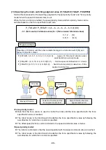
Page 212: ...This textbook was published in July 2018 Note that the specifications are subject to change without notice Issued July 2018 1807 MEE ...

Reviews: