


11
PARAMETER LIST
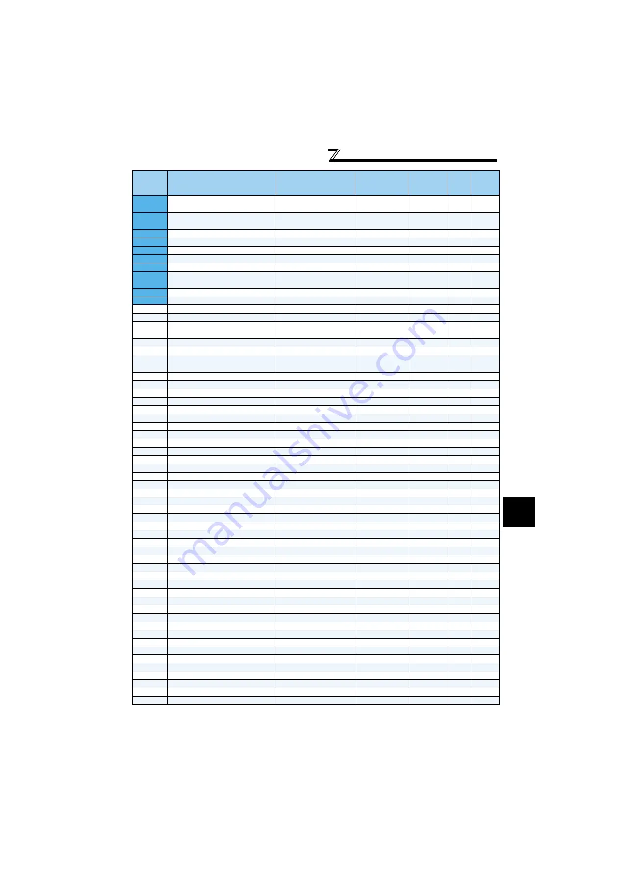
790
Initial winding diameter calculation start
point
400% to 600%
0.01%
400%
791
Initial winding diameter calculation
dead zone
0 to 50%
0.1%
1%
792
Accumulated amount
1 to 5000mm, 8888, 9999
1mm
160mm
793
Speed control P gain at a start
0 to 1000%
1%
60%
794
Speed control integral time at start
0 to 20s
0.001s
2s
795
Integral term limit at a start
0 to 100%
0.1%
2.5%
796
PID term limit at a start
0 to 100%
0.1%
2.5%
797
Rotation speed at winding diameter
calculated value activation
0 to 400Hz
0.01Hz
3Hz
798
Speed compensation bias
0 to 200%
0.1%
60%
799
Winding diameter monitor reference
1 to 6553mm
1mm
1000mm
800
Control method selection
0, 1, 2, 6, 9 to 12, 16, 20
1
20
—
802
Pre-excitation selection
0, 1
1
0
—
803
Constant power range torque
characteristic selection
0, 1
1
0
—
804
Torque command source selection
0 to 6
1
0
—
805
Torque command value (RAM)
600 to 1400%
1%
1000%
—
806
Torque command value
(RAM,EEPROM)
600 to 1400%
1%
1000%
—
807
Speed limit selection
0, 1, 2
1
0
—
808
Forward rotation speed limit
0 to 120Hz
0.01Hz
60Hz
—
809
Reverse rotation speed limit
0 to 120Hz, 9999
0.01Hz
9999
—
810
Torque limit input method selection
0, 1
1
0
—
811
Set resolution switchover
0, 1, 10, 11
1
0
—
812
Torque limit level (regeneration)
0 to 400%, 9999
0.1%
9999
—
813
Torque limit level (3rd quadrant)
0 to 400%, 9999
0.1%
9999
—
814
Torque limit level (4th quadrant)
0 to 400%, 9999
0.1%
9999
—
815
Torque limit level 2
0 to 400%, 9999
0.1%
9999
—
816
Torque limit level during acceleration
0 to 400%, 9999
0.1%
9999
—
817
Torque limit level during deceleration
0 to 400%, 9999
0.1%
9999
—
818
Easy gain tuning response level setting
1 to 15
1
2
—
819
Easy gain tuning selection
0 to 2
1
0
—
820
Speed control P gain 1
0 to 1000%
1%
60%
—
821
Speed control integral time 1
0 to 20s
0.001s
0.333s
—
822
Speed setting filter 1
0 to 5s, 9999
0.001s
9999
—
823
Speed detection filter 1
0 to 0.1s
0.001s
0.001s
—
824
Torque control P gain 1
0 to 200%
1%
100%
—
825
Torque control integral time 1
0 to 500ms
0.1ms
5ms
—
826
Torque setting filter 1
0 to 5s, 9999
0.001s
9999
—
827
Torque detection filter 1
0 to 0.1s
0.001s
0s
—
828
Model speed control gain
0 to 1000%
1%
60%
—
830
Speed control P gain 2
0 to 1000%, 9999
1%
9999
—
831
Speed control integral time 2
0 to 20s, 9999
0.001s
9999
—
832
Speed setting filter 2
0 to 5s, 9999
0.001s
9999
—
Speed detection filter 2
0 to 0.1s, 9999
0.001s
9999
—
834
Torque control P gain 2
0 to 200%, 9999
1%
9999
—
835
Torque control integral time 2
0 to 500ms, 9999
0.1ms
9999
—
836
Torque setting filter 2
0 to 5s, 9999
0.001s
9999
—
837
Torque detection filter 2
0 to 0.1s, 9999
0.001s
9999
—
840
Torque bias selection
0 to 3, 9999
1
9999
—
841
Torque bias 1
600 to 1400%, 9999
1%
9999
—
842
Torque bias 2
600 to 1400%, 9999
1%
9999
—
843
Torque bias 3
600 to 1400%, 9999
1%
9999
—
844
Torque bias filter
0 to 5s, 9999
0.001s
9999
—
845
Torque bias operation time
0 to 5s, 9999
0.01s
9999
—
846
Torque bias balance compensation
0 to 10V, 9999
0.1V
9999
—
847
Fall-time torque bias terminal 1 bias
0 to 400%, 9999
1%
9999
—
848
Fall-time torque bias terminal 1 gain
0 to 400%, 9999
1%
9999
—
849
Analog input offset adjustment
0 to 200%
0.1%
100%
—
Parameter
Name
Setting Range
Minimum
Setting
Increments
Initial
Value
Refer
to
Page
Customer
Setting


