49
PARAMETER LIST
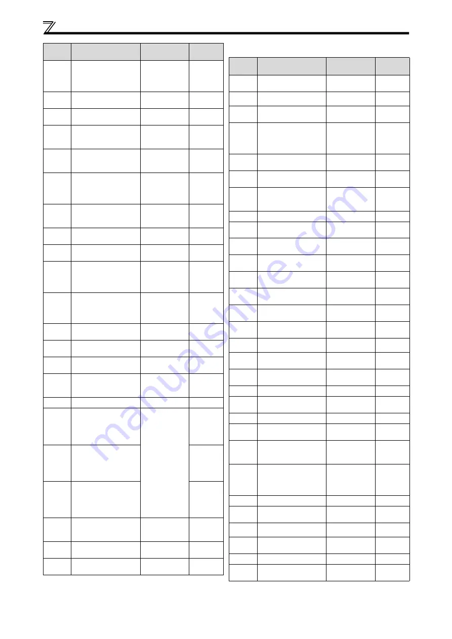
721
Starting magnetic
pole position
detection pulse
width
0 to 6000
μ
s,
9999
9999
724
Motor inertia
(exponent)
0 to 7, 9999
9999
725
Motor protection
current level
100% to 500%,
9999
9999
728
Device instance
number (Upper 3
digits) [E800-(SC)EPA]
0 to 419
0
729
Device instance
number (Lower 4
digits) [E800-(SC)EPA]
0 to 9999
0
737
Second motor
starting resistance
tuning compensation
coefficient 2
0% to 200%,
9999
9999
738
Second motor
induced voltage
constant (phi f)
0 to 5000 mV
(rad/s), 9999
9999
739
Second motor Ld
decay ratio
0% to 100%,
9999
9999
740
Second motor Lq
decay ratio
0% to 100%,
9999
9999
741
Second motor
starting resistance
tuning compensation
coefficient 1
0% to 200%,
9999
9999
742
Second motor
magnetic pole
detection pulse
width
0 to 6000
μ
s,
9999
9999
743
Second motor
maximum frequency
0 to 400 Hz,
9999
9999
744
Second motor inertia
(integer)
10 to 999, 9999
9999
745
Second motor inertia
(exponent)
0 to 7, 9999
9999
746
Second motor
protection current
level
100% to 500%,
9999
9999
759
PID unit selection
0 to 43, 9999
9999
774
Operation panel
monitor selection 1
[E800]
[E800-(SC)EPB]
1 to 3, 5 to 14,
17 to 20, 23 to
33, 35, 38, 40 to
42, 44, 45, 50 to
57, 61, 62, 64,
65, 67, 91, 97,
100, 9999
[E800-(SC)EPA]
1 to 3, 5 to 14,
17 to 20, 23 to
33, 35, 38, 40 to
42, 44, 45, 50 to
57, 61, 62, 64,
65, 67, 83, 91,
97, 100, 9999
9999
775
Operation panel
monitor selection 2
9999
776
Operation panel
monitor selection 3
9999
779
Operation frequency
during
communication error
0 to 590 Hz,
9999
9999
791
*3
Acceleration time in
low-speed range
0 to 3600 s,
9999
9999
792
*3
Deceleration time in
low-speed range
0 to 3600 s,
9999
9999
Para-
meter
Name
Setting Range
Initial
Value
*1
Parameter 800 to 999
Para-
meter
Name
Setting Range
Initial
Value
*1
800
Control method
selection
0 to 5, 9, 10 to
12, 19, 20, 40
40
801
Output limit level
0% to 400%,
9999
9999
802
Pre-excitation
selection
0, 1
0
803
Constant output
range torque
characteristic
selection
0 to 2, 10
0
804
Torque command
source selection
0, 1, 3 to 6
0
805
Torque command
value (RAM)
600% to 1400%
1000%
806
Torque command
value (RAM,
EEPROM)
600% to 1400%
1000%
807
Speed limit selection
0, 1
0
808
Speed limit
0 to 400 Hz
Gr.1: 60 Hz
Gr.2: 50 Hz
809
Reverse-side speed
limit
0 to 400 Hz,
9999
9999
810
Torque limit input
method selection
0 to 2
0
811
Set resolution
switchover
0, 10
0
812
Torque limit level
(regeneration)
0% to 400%,
9999
9999
813
Torque limit level
(3rd quadrant)
0% to 400%,
9999
9999
814
Torque limit level
(4th quadrant)
0% to 400%,
9999
9999
815
Torque limit level 2
0% to 400%,
9999
9999
816
Torque limit level
during acceleration
0% to 400%,
9999
9999
817
Torque limit level
during deceleration
0% to 400%,
9999
9999
820
Speed control P gain 1
0% to 1000%
60%
821
Speed control
integral time 1
0 to 20 s
0.333 s
822
Speed setting filter 1
0 to 5 s, 9999
9999
823
*4
Speed detection filter
1
0 to 0.01 s
0.001 s
824
Torque control P
gain 1 (current loop
proportional gain)
0% to 500%
100%
825
Torque control
integral time 1
(current loop integral
time)
0 to 500 ms
5 ms
826
Torque setting filter 1
0 to 5 s, 9999
9999
828
Model speed control
gain
0 to 1000 rad/s
100 rad/s
830
Speed control P gain 2
0% to 1000%,
9999
9999
831
Speed control
integral time 2
0 to 20 s, 9999
9999
832
Speed setting filter 2
0 to 5 s, 9999
9999
833
*4
Speed detection filter
2
0 to 0.01 s,
9999
9999
Summary of Contents for 800 Series
Page 10: ...4 INSTALLATION AND INSTRUCTIONS ...
Page 46: ...40 BASIC OPERATION ...
Page 64: ...58 INVERTER FAULT AND ALARM INDICATIONS ...
Page 70: ...64 SPECIFICATIONS ...


