


22
1
Select a new channel and clear that channel
(MEM→CHANNEL→FILE).
2
Set PROBE type to STRAIGHT.
3
Set RANGE TO 300 mm.
4
Set the known material velocity of 5920 m/s in VEL.
5
Set the gate so that it is positioned on the first
calibration echo (from 225 mm).
6
Read the sound path on the status line. If this value is
not equal to 225 mm, change the adjustment for the function
P-DELAY until it is at 225 mm.
7
Save the calibration result to current channel file.
22
5
This completes the calibration of the instrument to the material velocity of 5920 m/s with a calibration
range of 300 mm for the straight-beam probe used.
Case B: With Unknown Material Velocity
Use the semiautomatic calibration function of the instrument via the function group CAL for this
calibration case.
The distances between two calibration echoes must be entered. The instrument will then carry out a
plausibility check, calculate the material velocity and the probe delay, and automatically set the
parameters using the calculation result.
Calibration Process
1
Set the required display range in RANGE. The two calibration echoes selected must be
displayed on the screen. Set the range so that the second calibration echo is located on the right edge of
the screen.
2
Select the function group PDELAY(CAL→PDELAY).
3
Enter the distances of the two calibration echoes in S-REF1 and S-REF2.
4
Position one gate on the first calibration echo.
5
Position the other gate on the second calibration echo.
6
Press
key when CAL is selected to trigger the calibration.
The calibration is confirmed by the message “Calibration is finished”. The instrument will now
automatically determine the sound velocity and the probe delay and set the corresponding functions
accordingly. The value of the function P-DELAY will be set to the correct value.
If the instrument is not able to carry out any valid calibration on the basis of the input values and the
echoes recorded, a corresponding error message is displayed. In that case, please check the values of
your calibration lines and repeat the process of recording the calibration echoes.
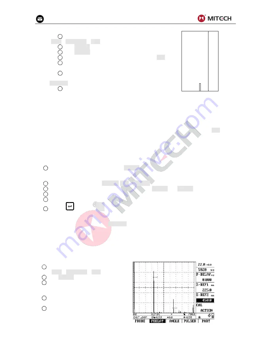
Example:
You are carrying out the calibration with a straight probe for the calibration range of 300 mm
1
Select a new channel and clear that
channel (MEM→CHANNEL→FILE).
2
Set PROBE type to STRAIGHT.
3
Enter the distances (thicknesses) of
the two calibration lines S-REF1 (225 mm) and
S-REF2 (450 mm).
4
Position one gate on the first
calibration echo.
5
Position the other gate on the second
calibration echo.


