


12
displayed); the receiver is connected with right, the pulse is connected with left.
Select the probe model step:
1
Activate the PROBE submenu (located in the CAL menu) by pressing the menu key below it.
2
Select the function item titled PROBE.
3
To change the probe mode, turn the knob. Each available probe mode is represented by an icon
on screen display whenever that probe mode is indicated.
4
The probe mode will be set to the last one displayed.
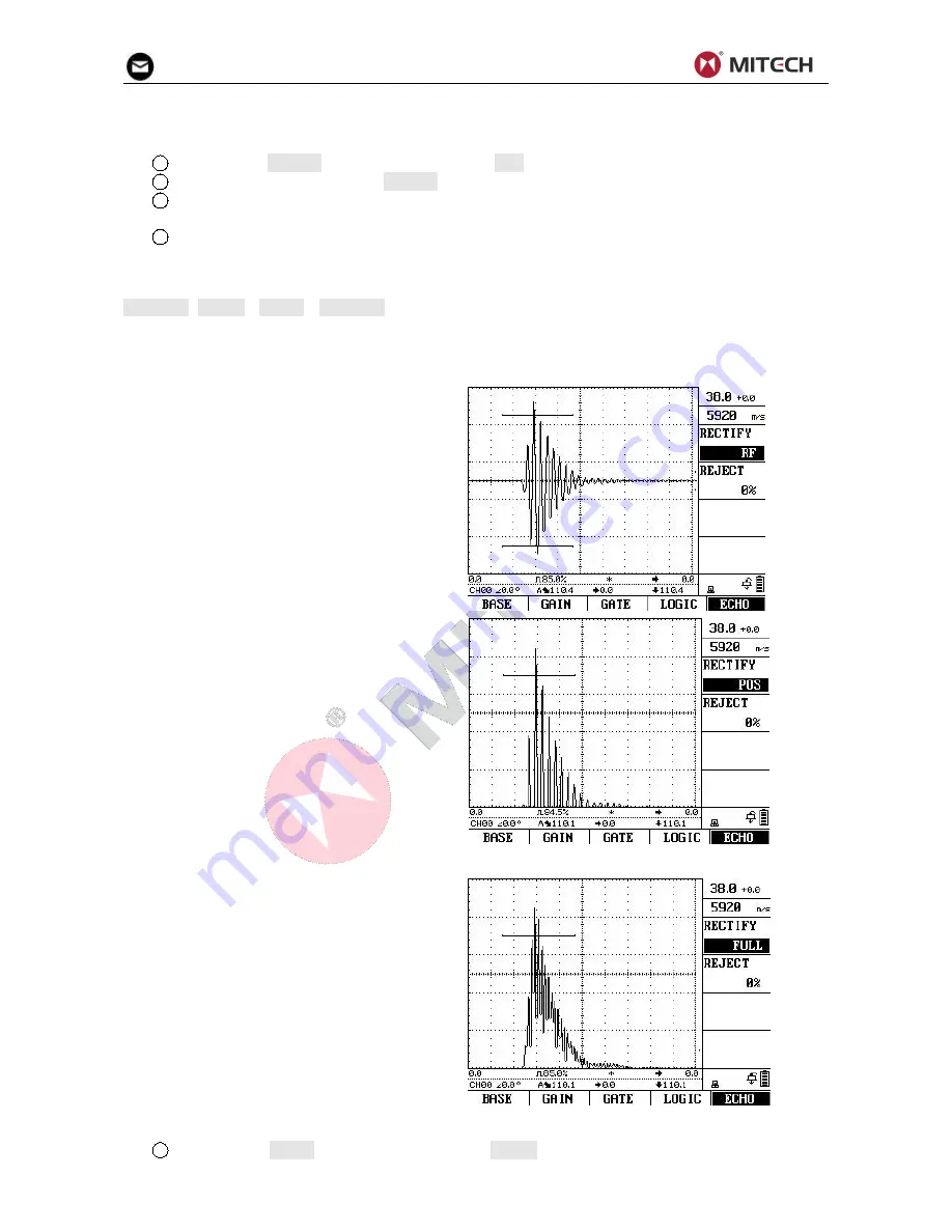
4.5 Selecting a Rectification Mode
You can select the rectification mode of the echo pulses according to your application in the function
RECTIFY (BASIC→ECHO→RECTIFY).
Rectification affects the orientation of the A-Scan on the display screen. The A-Scan represents the
pulse (echo) that’s returned from the material being tested to the instrument. The series of echoes looks
like the Radio Frequency (RF) signal.
Note that the RF signal has a negative
component below the axis, and a positive
component above the axis.
RF rectification is useful when evaluating a
probe.
RF rectification is forbidden when displaying
the DAC/AVG curves.
Positive Half Rectification means that only
the upper (positive) half of the RF signal is
displayed.
Negative Half Rectification means that only
the bottom (negative) half of the RF signal is
displayed. In the figure above, note that
even though it’s the negative half of the RF
signal, it’s displayed in the same orientation
as a positive component. This is only to
simplify viewing. The signal displayed in the
view identified as Negative Rectification is
the negative component of the RF signal.
Full-Wave
Rectification
combines
the
positive and negative rectified signals
together, and displays both of them in a
positive orientation. Full-wave rectification is
recommended for most inspections.
Use the following procedure to select a rectification mode
1
Activate the ECHO submenu (located in the BASIC menu) by pressing the menu key below it.


