background image

Imagestore User Manual  

AB Mixer 

Miranda Technologies Ltd 

Page 95 

AB Mixer (MIX-2000) 

Imagestore includes an integral AB video switcher option (MIX-2000) which 
is designed to be fed by an external router under automation control. The 
switcher provides cut and fade transitions with variable fade rates. 


Controlling the video switcher 

You can control the video switcher (cuts and x-fades from 1 to 999 fields) 
using: 


the Oxtel RCP remote control panel 


the Imagestore front panel 


programmable GPIs 


the RS422 and RS232 automation interfaces 

ƒ


analogue faders 


Summary of Contents for Imagestore 2

Page 1: ...Imagestore 2 User Manual 02359 11 April 2005 Software version 2 20 Miranda Technologies Ltd UK Tel 44 0 1491 820000 Fax 44 0 1491 820001 Email uksales miranda com Web www miranda com ...

Page 2: ...logies Ltd Copyright 1999 2005 Miranda Technologies Ltd All rights are reserved and under the copyright laws this manual may not be reproduced in any form in whole or in part without the prior written consent of Miranda Technologies Ltd Printed in the UK ...

Page 3: ... will replace or repair at its cost Oxtel Series equipment returned to the factory carriage and duty paid and insured by the sender Before returning any item for warranty repair a valid returns authorisation must be granted by Miranda Technologies Ltd All repaired goods will be delivered as instructed carriage and duty paid and insured by the sender Any warranty over and above that offered here is...

Page 4: ...ot apply a voltage to a terminal that is outside the range specified for that terminal 3 Ground the product Imagestore is grounded through the grounding conductor of the power cable To avoid electrical shock the grounding conductor must be connected to earth ground Before making connections to the input or output terminals of Imagestore ensure that the product is properly grounded 4 Do not operate...

Page 5: ...8 Provide proper ventilation To prevent Imagestore overheating provide proper ventilation 9 Do not operate with suspected failures If you suspect there is damage to Imagestore have it inspected by qualified service personnel Certifications and Compliances Imagestore has CE approval and complies with the standards detailed in EN50082 1 1992 and BS EN 60950 1992 Amd 3 Imagestore is fully Year 2000 m...

Page 6: ...f this protocol and other related issues are found in the appropriate documents shown in the following list Associated Publications Easysound User Manual Part No 01005 Media Conversion Software Part No 01033 Intelligent Panel Router User Manual Part No 01034 Oxtel Series Automation Protocol Part No 01035 Imagestore 3 2U User Manual Part No 02954 Easysound Standalone User Manual Part No 02349 Intui...

Page 7: ...ion with prompts from the display Where reference is made to a key the legend of the key will be shown in lowercase italics escape or enter or by the icons W and X The two line display provides a range of prompts in response to key presses Where reference is made to an actual display prompt this will be shown italicised e g Manual Override or image file erase ...

Page 8: ...centre Americas Telephone 9 00am 9 00pm EST 1 800 224 7882 techsupp miranda com Asia Telephone 9 30am 5 30pm JST 81 3 5730 2987 asiatech miranda com Europe Middle East Africa UK Telephone 10 00am 7 00pm CET 44 0 1491 820222 eurotech miranda com France only Telephone 9 00am 6 00pm CET Telephone 33 0 1 55 86 87 88 francetech miranda com www miranda com ...

Page 9: ... Oxtel Remote Control Panel Operations This section provides an introduction to Miranda Technologies Ltd s Oxtel RCP for new users It identifies the user controls and explains how they are used It describes the way the panel may be used to control more than one Miranda Technologies Ltd unit through an Intelligent Panel Router IPR The full range of remote control panel functions available when used...

Page 10: ...anel controls It identifies the procedure for saving these settings to floppy disk and recovering the setting from that disk Installation and Integration This section contains details of the unit interconnections and interfaces It describes all the set up procedures required for a successful installation including reference source selection internal timing and synchronisation set up Support The su...

Page 11: ...ndix 2 Glossary This appendix contains a guide to the terms and abbreviations found within this user guide Appendix 3 Menu Trees This appendix contains a series of diagrams representing the front panel operation and configuration menu trees Appendix 4 Custom Configuration Notes This appendix provides blank pages that may be used to record useful unit configuration data ...

Page 12: ...Preface Imagestore User Manual Page 12 Miranda Technologies Ltd ...

Page 13: ...iated Publications 6 Symbols and Conventions 7 Contacts 8 Manual Structure 9 Overview 9 Front Panel Operations 9 Oxtel Remote Control Panel Operations 9 AB Mixer 9 Squeezy DVE 9 Easysound Audio 10 Emergency Alert System 10 Imagestore Intuition 10 Configuration 10 Installation and Integration 10 Support 10 Appendix 1 Product Specification 11 Appendix 2 Glossary 11 Appendix 3 Menu Trees 11 Appendix ...

Page 14: ... and Distribution 30 Image Editing 30 Transmission 31 Animated Images 31 Polyphoto Playlist and Image Clean Up 31 Clock Insertion 32 Squeezy Digital Video Effect DVE 32 AB Mixer 33 Embedded Digital Audio Mixer 33 Digital Audio Storage 33 Timing Control and Automation 33 Remote Control Panels 34 Mechanical Bypass 34 Options 34 Checking Installed Options 35 Front Panel Operations 37 Controls 37 VFD ...

Page 15: ...Fade Transition Rates 47 Preview Operations 48 Loading Images 48 Live Input 49 Loading from FDD 49 Library Images 51 Image Load Mode 51 Wipe Load 51 Clean Load 51 Cut Load 51 Saving Images 52 Grabbing Images 53 Editing Images 54 Adjusting Clip Gain and Transparency 55 Set Position 56 Masking Images 56 Key Parameters 57 Setting the Preview Output 59 Cascade Mode Operations IS2 Only 61 Midground and...

Page 16: ...enu Keys 73 Load 73 Save 73 Edit 73 Play List 73 Setup 74 Next Del 74 Alphanumeric Keypad 74 Fade to Black 74 Previous Prev 75 Next 75 Take and Swap 75 Cut Fade 76 Rate 76 FG Keyer and MG Keyer 76 Channel Set 76 Soft Keys 76 Rotary Controls 76 Swap Preview Mode Operations 77 Transmission Control 77 Program Fade to Black 77 Program Image On Air Off Air 78 Exchanging Program and Preview Images 78 Se...

Page 17: ...Add to Current Playlist 84 Playlist 85 Set Up 86 RCP Parameters 86 Transition Rates 87 Preview Output Set 87 Cascade Mode Operations 88 Transmission Controls 88 Program Fade to Black 88 Foreground Midground Images On Air 88 Selecting Transition Speed 89 Cut Fade Selection 89 Loading Images to Foreground and Midground 89 Load from the Image Library 89 Loading a Live Image 90 Saving Images 90 Editin...

Page 18: ...agestore front panel 97 Cut A B 97 Fade A B 98 Transition Type 98 Set mix rate 99 Wipe softness 100 Colour V fade 100 GPIs 101 GPI inputs 101 GPI outputs 101 RS422 and RS232 automation interfaces 101 Analogue faders 102 Squeezy DVE 105 Squeeze modes 105 Squeeze presets 108 Controlling Squeezy DVE 108 Using Squeezy with the Oxtel RCP 109 Imagestore front panel 110 GPIs 111 Automation control system...

Page 19: ...ode configuration 120 Mode 120 Audio Follow Video 121 A Input B Input 121 VO1 Input VO2 Input 122 VO1 Settings VO2 Settings 123 Embed OP Settings 125 Effects Send 125 AB Mix and VO mode 126 Two Voice Overs mode 127 Data 127 AB Mix and VO mode 128 Two Voice Overs mode 128 Front Panel Control 129 Programme 129 Front panel audio metering 130 Preview 130 Audio model mode with the Oxtel RCP 131 AB Mix ...

Page 20: ...ion 138 Rear panel connections 139 AES input 139 AES output 141 AES GPI control 141 Cross connecting GPIs 143 Caution 143 Connection of external analogue faders 143 Input to GPI 143 Output from GPI 144 GPI Control of Audio Model Shuffle 144 Example 146 Installing Easysound 147 Emergency Alert System 149 EAS Receivers 149 Baud Rates 150 Load EAS EAS On 150 Unload EAS EAS Off 150 EAS logs 150 Images...

Page 21: ...vironment 159 Rear Panel Connections 159 Serial Remote Control 161 Oxtel RCP 161 RS232 161 RS422 162 SDI Control Port 162 Pinout Functions 163 Connection of Analogue Faders 164 Connection of General Purpose Interfaces GPIs 164 Input to GPI 164 Output from GPI 165 Connection of LTC 165 KYBD and VGA Connections 165 Set Up Procedures 165 GPI Setup Commands and Macros 166 GPI Inputs Assign 166 Assigni...

Page 22: ... Commands and Menus 185 Faders Enable Disable 185 Faders Setup 186 Faders 187 Show Fader Status 188 File Facilities 188 Configuration Save 188 Configuration Load 189 Diagnostic Save 189 Load System Codes 190 Installing system codes 190 What are licence codes 191 System Information 192 On Screen Information Swap Preview Mode 192 System Status 193 Licences 193 Error Log 193 View Licence 194 Set Time...

Page 23: ...stment 201 Measurement and Test Equipment 202 SDI BGnd A Reference 202 Analogue Reference Black and Burst 203 Support 205 Product Support 205 Warranty and Non Warranty Repairs 205 Obsolescence 206 Upgrades 206 Service Visits 206 Equipment Loans 206 Training 206 Web Page 207 Returns Procedure 207 Transit Packaging 207 Appendix 1 209 Imagestore specifications 209 SDI Inputs and Outputs 209 Analogue ...

Page 24: ...nmental 211 Oxtel RCP 211 Mechanical 211 Environmental 211 Power Requirements 211 Appendix 2 213 Glossary 213 Appendix 3 215 Menu Trees 215 Swap Preview Mode menu tree 215 Cascade Mode menu tree 216 Set Up Menu Tree 216 System Set Up Sub Menu Tree 217 Appendix 4 219 Custom Configuration Notes 219 ...

Page 25: ...ies may be extended to include digital audio mixing storage and play out Applications Imagestore is typically used to insert a still or animated logo a channel identification a programme schedule an advertisement an on screen clock an emergency image or a combination of any two of those Each of these resources may be brought on air from Imagestore s 400 image memory optionally 2000 or 4000 image A...

Page 26: ...ce provides for the rapid loading of images and animations over either a co axial or twisted pair network using MCS This interface also enables the transference of images between a PC workstation and Imagestore using Miranda Technologies Ltd s MS Windows NT based Media Distribution System MDS The MDS software provides for transfer and management of still images animations and clocks Imagestore Sol...

Page 27: ... of the images in the hard disk image library to be previewed and edited without affecting the programme output The standard SDI preview output may be replaced with an optional analogue PAL NTSC output although this option uses an 8 bit DAC and is intended for monitoring purposes only The preview output may also be used to view system information and where the Edit Pack option is installed thumbna...

Page 28: ...o Programme Video Preview Video Key Video Fill Video Ether net Cascade Mode Concept In Cascade mode the two keyers are arranged in series as shown above This configuration allows two images to be keyed simultaneously but independently over the background video Cascade Mode provides a more restricted preview capability whilst still providing the ability to view images prior to transmission ...

Page 29: ...Boot Up Sequence Once power is applied Imagestore boots automatically and the complete process takes about 50 seconds The unit first checks to see if there is a disk in the floppy drive and if it finds one it will attempt to boot from that disk Miranda Technologies Ltd issues specialised floppy disks for use as part of the boot up sequence when software upgrades are being implemented No other disk...

Page 30: ...ies from Miranda Technologies Ltd s Media Conversion Software or other Miranda Technologies Ltd units can be loaded in the same way The Media Conversion software allows large animations and images to be saved across multiple floppy disks using loss less compression to reduce the number of disks required Frames may be grabbed from SDI video using the Fill and Key ports An image clean up feature to ...

Page 31: ...n builder software provided as part of the Media Conversion Software package supplied with Imagestore Component images are imported into the animation builder utility from 32 bit Targa image files thus allowing components to originate from almost any computer graphics system Polyphoto Playlist and Image Clean Up The Edit Pack option provides the additional features of polyphoto playlist and image ...

Page 32: ...way as animations and static logos Bugclock images behave like all other images with respect to positioning transparency and masking controls Previewing behaviour is the same as with other clips and images and will show the clock running where appropriate All existing GPI and automation commands that apply to still images and animations function identically for clocks A Bugclock image uses a singl...

Page 33: ...nd playout option for Imagestore With Easyplay broadcasters can associate sounds to image files creating a whole new range of possibilities for musical logos and sound enhanced captions Easyplay requires the Easysound option to be fitted to Imagestore and the system may be networked with the Media Distribution System Timing Control and Automation Imagestore is designed to be easy to install One li...

Page 34: ...MF 001 frame To save space and simplify control the remote control panels can control more than one Imagestore when used with the Intelligent Panel Router IPR The IPR also allows a single Imagestore to be controlled by multiple remote control panels in different locations Mechanical Bypass In the event of power loss to the Imagestore or failure of an internal power supply the mechanical bypass opt...

Page 35: ...EP1 Easyplay digital audio storage and playout system MEM 200A Audio storage expansion to 200 minutes Not with MEM 4000 Imagestore Imagestore 2 licence Solo Imagestore 2 SOLO licence EAS1 Emergency Alert System Checking Installed Options The Imagestore can display the internal options installed using either its front panel display or on a monitor connected to its rear panel PVW output Front Panel ...

Page 36: ...de From the boot up menu press the right arrow keyX to move the brackets from manual to set up With set up selected press the enter key to display the set up menu Press the right arrow key X until that the words on screen info appears on the second line of the display Press the enter key once and if a monitor is connected to the preview output it will display an on screen summary of the options to...

Page 37: ...py disk drive four push button control keys and a vacuum fluorescent display VFD Local control of the unit is menu driven using a combination of the push button keys together with options displayed on the VFD The upper key of the group is identified on the panel as the escape key and the bottom key is identified as the enter key Left and right keys W X are used to move a cursor left and right acco...

Page 38: ...sive pressing of the key will bring the display to the start up menu The enter key is used to accept the menu item currently shown as selected by being enclosed in brackets Left and Right Arrow Keys W X Left and right arrow keys W X may be used to cursor left and right respectively along a displayed menu branch to select a function When a selection of parameters is offered these keys may be used t...

Page 39: ...iles Any image stored within the image library may be erased using the image file erase option To erase an image select the Manual option from the boot up menu and using the arrow keys W X display the image file erase option shown below Press enter and use the left and right arrow keys W X to step through the valid file names Once the appropriate image name is displayed and the enter key is presse...

Page 40: ...to apply that selection Three options are made available A Background Fill and Key Use the arrow keys W X to select the appropriate input and then press the enter key to apply that selection In each case the display will indicate whether SDI video or colour is currently selected To change the current setting use the arrow keys W X to select the choice and press the enter key to apply the selection...

Page 41: ... image library under the name V000 oxt and it replaces any other foreground image that is currently being displayed Having selected manual from the boot up menu use the arrow keys W X to display the emergency to air option and select it by pressing the enter key Having selected emergency to air confirm the intention by pressing the X arrow key to select Yes then pressing the enter key This action ...

Page 42: ...in the alternate mode The modes are identified as Swap Preview IS2 and Solo and Cascade IS2 only Changing Imagestore s mode is described in the Set Up section of this manual To check the mode of Imagestore select manual operate from the boot up menu With operate displayed press the enter key The first line of the display will now indicate Imagestore s current mode by showing either Swap preview Op...

Page 43: ...the options manual set up operate programme cut sw ap fade sw ap cut up dow n fade up dow n FTB on off transition rates Cut Swapping Images The cut swap feature causes the image loaded on the programme channel to be exchanged with the image from the preview channel The action is instantaneous Select manual operate programme cut swap from the boot up menu to locate the feature Press the enter key t...

Page 44: ...mage Select manual operate programme fade swap from the boot up menu to locate the feature Press the enter key to action a fade swap When the operation takes place the arrow may change from to During the transition the arrow is replaced by the intermediate state symbol acknowledging the fade is taking place No other change can be detected on the VFD display which remains showing the same menu sele...

Page 45: ...e Up Down The fade up down feature causes the current image to be faded from air and when there is no on air image a subsequent command will fade the image to air Select manual operate programme fade up down from the boot up menu to locate the feature Press the enter key to action a fade up or a fade down When the operation takes place the arrow symbol will change from fade up to fade down During ...

Page 46: ...e The replacement rate is determined by the setting under transition rates see below Select manual operate programme FTB on off from the boot up menu to locate the feature Press the enter key to action a FTB on off When FTB is on the B symbol will appear next to the up arrow When FTB is off no B symbol is displayed During the FTB transition the intermediate state symbol appears next to the arrow a...

Page 47: ...ate the feature When transition rates is selected and applied two further options become available from the Adjust Rates menu the Fade rate the Fade to Black FTB rate Select the appropriate option using the arrow keys W X and apply the selection using the enter key The current setting will be shown and pressing the escape key will exit the set up leaving the value unchanged To change the current s...

Page 48: ...oad image feature enables the user to load the preview store with an image from Imagestore s library from a floppy disk in the 3 disk drive or a live image from the Fill and Key SDI inputs Images loaded from the library or FDD may be used immediately or edited and saved Select manual operate preview load image from the boot up menu to locate the feature manual set up operate programme preview load...

Page 49: ...loppy disks to be DOS formatted 1 44MB and the files to be in a format shown in the following table In each case the image file extension must match the image format When the load from FDD prompt displayed and a disk is in the drive press the enter key to load the file As the disk is read each file on the disk is examined in turn and each image file found is copied into the image library and loade...

Page 50: ...used the MCS tools also apply loss less compression to the file to reduce the number of disks required To load an image or animation held on multiple floppies put the first disk in the drive select the load from FDD option and press enter Imagestore will prompt you for the each subsequent disk as it is required The floppies can be presented in any order Imagestore will automatically combine and de...

Page 51: ...ad mode from the boot up menu then press enter Using the left and right arrow keys W X select one of the following options pressing the enter key to accept the choice Wipe Load As the image animation is loaded into the preview store it is also displayed via the preview output Larger files may be displayed gradually until the image is complete Animations will be displayed frame by frame until the e...

Page 52: ...be saved together with its mask allowing the option for the mask to be subsequently enabled disabled or modified Where Cropped is selected only the image within the masking area will be saved thus creating a smaller file but permanently restricting the image to the boundaries of the mask The resultant prompts from the Full Image and Cropped options are identical In each case a choice is offered be...

Page 53: ...oppy disk changes Upon completion of the process the display returns to the Save Image menu Grabbing Images The Grab Image feature enables the user to load the preview store directly from the external SDI Fill and SDI Key inputs Once loaded the image can be edited and stored or used immediately without change Select manual operate preview grab image from the boot up menu to locate the feature Pres...

Page 54: ...ab Image mode by pressing the escape key The grabbed image will remain held in the preview store Editing Images The image editor enables the user to adjust a number of parameters all of which affect the visual appearance of an image Once changed the image may be used immediately or saved for later use The following four groups of parameter may be changed Clip Gain and Transparency Set Position Mas...

Page 55: ...own in the middle The right and left arrow keys W X are used to increase and decrease the setting respectively The setting is applied by pressing the enter key Once set the display moves on to the next parameter Adjust Gain The adjustment is made in exactly the same way as for Clip Once Gain is set the display moves on to the final adjustment Adjust Transparency which is set in the same way as Cli...

Page 56: ...top left corner of the visible background and the top left corner of the image For a horizontal adjustment the setting is the number of pixels that the image is to the right of the top left visible corner of the screen Negative values are displayed if the image is moved to the left of that top corner reference where part of the image would be outside of the visible screen area For a vertical adjus...

Page 57: ...ther normally or inverted Source selects between using no keying a separately stored key signal or an internal key signal derived from the stored picture image Type selects between full or linear keying modes For Type the mode Full Key sums the background with the key signal removed to the foreground The foreground is only passed where the key signal is present This mode is used with self luma key...

Page 58: ...cause the Fill image to be opaque with no background appearing through Intermediate keying levels will produce a pro rata transparency effect Setting the sense option to invert reverses this effect and white level key signals now create a fully transparent Fill image with black level signals producing an opaque Fill image Source When the source option is set to separate the key data is derived fro...

Page 59: ...nnel fill image Program Key Programme Channel key image Preview Fill Preview Channel fill image Preview Key Preview Channel key image Fill Fill input Key Key input Program Output Programme SDI Output Program Preview Preview SDI Analogue Output Normal Setting A Background Background input Presmaster Preview IS2 only B Input B input AB Mixer only AB Mix AB mixer output AB Mixer only Select manual op...

Page 60: ...ed the left and right arrow keys W X are used to display each of the nine options for the preview output When the appropriate selection is displayed press the enter key to apply that choice The output setting should be returned to Program Preview once monitoring is complete to ensure operation of the Polyphoto feature ...

Page 61: ...some ability to view an image prior to transmission The two keyers are identified as the midground MG keyer and the foreground FG keyer Both layers operate identically but the image editor feature cannot be used whilst the MG layer is on air If the MG layer is in use when a user requires the image editor feature the MG layer would have to be taken off air first To change between Swap Preview or Ca...

Page 62: ...d a single description is given operate select midground select foreground select preview output set select image editor manual set up Note AB Mixer and Audio selection may appear depending on licences installed Having selected the midground or foreground keyer the sub menus are as follows select midground or foreground cut up down fade up down load image transition rates FTB on off ...

Page 63: ... locate the cut up down and fade up down features Press the enter key to action a cut fade up or a cut fade down When the operation takes place the arrow symbol will change from cut fade up to cut fade down No other changes can be detected on the VFD display which remains showing the same menu selection for further cut fade up down operations Switching Fade to Black On and Off The FTB on off featu...

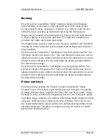
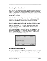
Page 64: ... Turning the foreground fade to black FTB to ON will force the programme output of the Imagestore to black With the midground FTB ON any foreground image that is currently on air will still be seen over the black output of the midground keyer Loading Images The load image feature is used to load images from following the floppy disk the image library or live from the fill and key input ports The a...

Page 65: ...lies even if the image is not on air To regain the grab facility a new image must be loaded into the channel that has live image selected Although the live input function is normally independent of the Background SDI signal it should be noted that if the Imagestore is using the SDI digital signal as a clocking source that signal must be present Press the enter key and the Imagestore will begin to ...

Page 66: ...d into the midground or foreground store Select set up image load mode from the boot up menu then press enter Using the left and right arrow keys W X select one of the following options pressing the enter key to accept the choice Wipe Load As the image animation is loaded into the midground or foreground store it is also displayed via the appropriate output Larger files may be displayed gradually ...

Page 67: ... become available from the Adjust MG Rates or Adjust FG Rates menus these are the fade rate and the FTB rate Select the appropriate option using the arrow keys W X and apply the selection using the enter key Change the current setting using the left and right arrow keys W X to adjust the appropriate frame rate up or down Press the enter key to apply the new setting Pressing the escape key will exi...

Page 68: ...nd Background input Foreground Fill Foreground fill image Foreground Key Foreground key image Midground Fill Midground fill image Midground Key Midground key image Fill Fill input Key Key input Input B Input B AB Mixer only AB Mixer AB Mixer output AB Mixer only Program Output Programme SDI Output Program Preview Preview SDI Analogue Output normal setting Presmaster Preview After the preview outpu...

Page 69: ...n Cascade mode when the midground keyer is not on air Ensure that there will be no requirement for the midground image to be taken on air during an editing session When using the Cascade mode editing features refer to the editing images section of Swap PVW Mode Preview Operations given in earlier paragraphs of this guide ...

Page 70: ...Front Panel Operation Imagestore User Manual Page 70 Miranda Technologies Ltd ...

Page 71: ...e time of installation to avoid accidental operation but this manual describes all the potential features Further information and support on the Unit is available from the Miranda Technologies Ltd Support Desk at the phone number on the cover of this manual Miranda Technologies Ltd s Intelligent Panel Router IPR enables one or more Oxtel RCP s to operate multiple Imagestore Logostore or Playstore ...

Page 72: ...mp within each push button switch will illuminate in turn The following paragraphs describe the use of the controls for new users Display The LCD display provides interactive access to the control menus of the connected equipment The basic display of the RCP is always provided shortly after power is first supplied and can be reached at any time by repeatedly pressing the ESC key The brightness and...

Page 73: ... not illuminated is unavailable either because the feature is not currently appropriate or the unit connected does not support that feature Pressing any available illuminated menu key results in the appearance of an operational display Use of these features is described in the section relating to the product connected to the remote control panel Load The LOAD key provides access to the image loadi...

Page 74: ...r use When using the keypad to enter a file name use the set up RCP feature to select the buttons for alpha or numeric mode Where alpha is selected press the key once for the first character twice for the second alphabetic character and so on When the appropriate character is displayed pressing a different alphanumeric key will automatically move the entry cursor Where the same key is to be re use...

Page 75: ...from the image library In play list mode the image loaded will be the following image in the play list In polyphoto mode the NEXT key will move the cursor flashing yellow dot to the following thumbnail image Take and Swap The TAKE light is lit when the image selected on the programme output is on air The light is out when the programme image is cut or faded down The TAKE key can be used to take lo...

Page 76: ...estore that is operating in the Cascade mode FG is an abbreviation of foreground and MG is an abbreviation of midground The keys are used to determine the keyer affected by current operations Channel Set The CHAN L SET key is only effective when the RCP is used via an Miranda Technologies Ltd Intelligent Panel Router Pressing the CHAN L SET key will provide access to the Channel Set menu Soft Keys...

Page 77: ...sion Control The group of buttons in the bottom right hand corner of the controller is used to take images on and off air and to exchange images between the program and preview keyers The use of these buttons does not involve any prompts on the controller LCD Note The SWAP button is used to determine the action of the TAKE button and pressing it will cause the legend above the SWAP button to eithe...

Page 78: ...tores the condition of the SWAP button is crucial Ensure that the legend marked SWAP above the swap button is illuminated If it is not illuminated press the SWAP button to illuminate the legend With the SWAP legend illuminated pressing the TAKE button exchanges the Program and Preview images Selecting Transition Speed Each time the Rate button is pressed the rate selection will step through its op...

Page 79: ...methods is to be used for searching Images using numeric filenames example V123 OXT may be loaded by simply entering the 3 digit value example 123 at the keypad and pressing ENTER The rotary control associated with Letter is a coarse control quickly scrolling through the library images displaying the first file or title starting with each alphanumeric character Once the starting character has been...

Page 80: ... to the preview store will cancel the live condition Grabbing an Image To grab an image press the right hand soft key identified on the display as Grab This will result in a new display being presented Pressing the Grab soft key will freeze the frame and the frozen image will be displayed at the preview output The Previewing prompt will be replaced by a Grabbed prompt If the image is not quite rig...

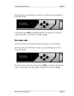
Page 81: ...the option displayed above it on the LCD The Letter and File rotary controls are used for coarse and fine scrolling through the existing image library If an existing image is to be overwritten then press ENTER with the name displayed The display will request confirmation of the save and add the words Cancel or Overwrite Use the keypad to enter a new file name and press the Title soft key to move t...

Page 82: ... display will appear The horizontal and vertical position of the image may now be adjusted using the rotary controls positioned above the on screen Horiz and Vert prompts A numeric display directly underneath the positional prompts indicates the settings so that normal settings may be swiftly repeated With the Edit Position menu displayed the left hand soft key may now be used to select the Set Ke...

Page 83: ...ositioned above the appropriate on screen prompt Numeric displays directly underneath the display prompts indicate the current mask settings Press the soft key beneath the Left Right on screen prompt and the Set L R Mask display will appear The Left and Right masks may now be adjusted using the rotary controls positioned above the appropriate on screen prompt Numeric displays directly underneath t...

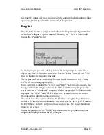
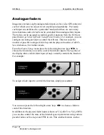
Page 84: ...ing an Oxtel RCP remote controller On the RCP press the ESC button repeatedly to ensure that the ESC button illumination is extinguished To view the polyphoto display press the POLY button on the RCP and the display will appear on the preview monitor Adjusting the options presented after pressing the SETUP button can change the polyphoto layout and background see the SETUP description A red dot ap...

Page 85: ...The keypad and cursor control may be used to edit the name or title Press ENTER to load the appropriate file When a playlist is loaded the NEXT and PREV keys may be used to step through each of the images in turn or the POLY button may be pressed to reveal a screen of thumbnail images of files in the playlist With thumbnails displayed the NEXT and PREV keys may be used to move the cursor flashing ...

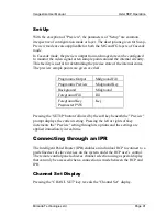
Page 86: ...mage to the playlist press the soft key beneath the Add screen prompt Set Up The Set Up button is used to provide access to the Setup menu that controls a range of RCP parameters RCP the Polyphoto display Poly the keyer fade and programme fade to black rates Rate and the preview output set Preview RCP Parameters To adjust the RCP parameter settings by press the soft key below the RCP prompt The LC...

Page 87: ...sses cycle the entry through its options without advancing the cursor When the desired character is displayed pressing a subsequent button will advance the cursor If the same button is to be used for the following character then press the NEXT button to advance the cursor Press the ENTER button to conclude the entry Transition Rates Within the Set Up menu the keyer fade rate and the FTB fade rate ...

Page 88: ...sing the Fade to Black button causes the appropriate keying layer output on air to fade to full screen black When the output is already faded to black selection causes the same layer output on air to fade from a full screen black image to the previously displayed image The replacement rate is determined by the Rate setting Turning the foreground fade to black FTB to ON will force the programme out...

Page 89: ...hown illuminated above the button This determines the effect that is used to bring images to air Loading Images to Foreground and Midground Once the MG KEYER or FG KEYER button has been selected the procedure for loading images is identical and the following description is equally valid for both Press the appropriate keyer button FG KEYER for foreground or MG KEYER for midground Press the LOAD but...

Page 90: ...keyer Loading a Live Image To load the layer image at the Fill and Key video inputs directly to the programme output press the left hand soft key identified on the display as Live The video input will then be passed directly to the either the FG or MG keyer and appear on the PGM output The display will indicate Live Loaded To cancel or override the live load condition select an image from the Imag...

Page 91: ...me Output Midground Fill Programme Preview Midground Key Background Midground Foreground Fill Fill Foreground Key Presmaster PVW Key Pressing the SETUP button followed by the soft key beneath the Preview prompt displays the current setting Pressing the left or right soft key increments the Preview setting through its options and the settings are applied immediately in real time Connecting through ...

Page 92: ...e Intelligent Panel Router IPR The IPR allocates each Oxtel RCP with an identifying name In the example above the identifier is comprised of a number RCP1 and a given name Prep Area Current The Current field shows the unique number and given name for the channel currently connected to the RCP In the example above the channel number shown is 200 and the given name is Imagestore 2 New The New displa...

Page 93: ...of available connections History Pressing the left hand soft key positioned beneath the History on screen legend causes the New selection to step through that last ten connections made by the user excluding duplicates of the current position Numeric Keypad The numeric keypad may be used to enter the required channel number The channel number is allocated to a channel at system installation Channel...

Page 94: ...een as the Current channel If another Oxtel RCP already has a connection to this channel the user will be informed of this with a message indicating which other RCP is currently connected and given the choice as to whether the current connection should be broken The appropriate soft key beneath the prompt legends should be pressed The user who has had his connection broken will have a message disp...

Page 95: ...e fed by an external router under automation control The switcher provides cut and fade transitions with variable fade rates Controlling the video switcher You can control the video switcher cuts and x fades from 1 to 999 fields using the Oxtel RCP remote control panel the Imagestore front panel programmable GPIs the RS422 and RS232 automation interfaces analogue faders ...

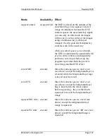
Page 96: ... RCP To use the MIX 2000 AB Mixer from the RCP choose Mixer press the appropriate soft key from the top level menu see above You can now press TAKE to switch toggle between the A and B inputs according to the transition type fade cut and rate When you choose wipe the V fade transition is enabled ...

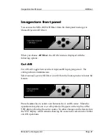
Page 97: ...ggle between the A input and B input going on air The cutting action is instantaneous Select manual operate AB Mixer cut A B from the boot up menu to locate the feature Press the enter key to action a cut between the A and B source When the operation takes place an A or a B symbol will appear on the top line of the VFD display showing the active source No other changes can be detected on the VFD d...

Page 98: ... fade between the A and B source When the operation is complete an A or a B symbol will appear on the top line of the VFD display depending on the active source During the transition the intermediate state symbol is displayed acknowledging the fade is taking place No other change can be detected on the VFD display which remains showing the same menu selection for further fade A B operations Transi...

Page 99: ...he list of entries To select an entry press enter To go back a level press escape Set mix rate Sets the mix rate i e the duration of the mix between 1 and 999 frames Select manual operate AB Mixer set mix rate from the boot up menu to locate the feature Press the enter key then use the arrow keys W X to increase or decrease the value To select the value press enter To go back a level press escape ...

Page 100: ...ect the value press enter To go back a level press escape Colour V fade This option allows the user to change the V fade colour from the default factory setting of black to any colour of their choice by adjusting the RGB values Select manual operate AB Mixer V fade colour from the boot up menu to locate the feature Press the enter key then use the arrow keys W X to increase or decrease the colour ...

Page 101: ...ies To select an entry press enter To go back to the top level list press escape Note The GPI Outputs Assign menu does not include sub menus go to Set up GPI Setup GPI Outputs Assign GPI inputs See GPI Setup Commands and Macros for a complete list of the GPI input commands which are available from the AB Mixer sub menu GPI outputs GPI outputs for Mixer at A and Mixer at B are provided See GPI Comm...

Page 102: ...trol the AB mix This increases the number of possible analogue faders beyond the physical number of ADCs See Addendum 1 for further details From the Faders Setup menu press the left and right arrow keys W X to choose the functions you want to control from fader inputs The top line of the display shows which fader input if any currently controls the function For example To assign a fader input to c...

Page 103: ... prompted to enable or disable the fader invert the polarity of the displayed fader prevent sudden jumps caused by accidental fader movements by enabling fader pickup the fader must be moved through the current position before you take control Note The list of controllable functions and the set of fader inputs available to control them will depend on the options fitted to your version of Imagestor...

Page 104: ...AB Mixer Imagestore User Manual Page 104 Miranda Technologies Ltd ...

Page 105: ... applications such as over the shoulder news transitions as well as squeezes for credits news flashes sports results and schedules Squeeze modes Imagestore operates in cascade mode and swap preview mode these are always available irrespective of how your system is set up The following list includes details about all the Squeeze modes including when each mode is available for example in cascade mod...

Page 106: ...th of the AB mixer the A input signal is revealed as the B input is squeezed when you use the mixer to fade between A and B the squeezed image is faded up and down squeeze and reveal swap preview the DVE is placed on the A input or if fitted the output of the AB mixer the squeeze reveals the current fill contents of the main and preview stores note that this mode inverts the operation of the keyer...

Page 107: ...view store when you subsequently perform a cut swap or fade swap the program layer takes both the preview store image and the DVE effect reveal MG cascade this is the same as squeeze and reveal see above except the midground layer is revealed while the foreground layer logo is keyed over the result reveal FG cascade this is the same as squeeze and reveal see above except the midground layer bug is...

Page 108: ...image crop widths All the numbers in a preset are represented as percentages these numbers are based on a screen with a width and height of 100 You can use up to 100 presets Note that preset zero is a full screen preset and cannot be edited or overwritten Controlling Squeezy DVE You can control Squeezy DVE using the Oxtel RCP remote control panel the Imagestore front panel programmable GPIs the Im...

Page 109: ...lected loaded squeeze preset LOAD and EDIT pressing these buttons enables you to select load a squeeze preset and then edit that preset for example you can edit the size of the image and the x y position of the image and you can crop the image note that any edits are automatically saved to load a squeeze preset enter the number of the preset and then press ENTER note that when you load a preset a ...

Page 110: ...ueezy menu enable you to select presets edit presets change squeeze mode perform DVE moves For example Squeeze option Used to do squeeze toggle between the currently selected DVE preset and the full screen clear squeeze return to the full screen select preset select a numbered preset as each preset is displayed the DVE jumps to show the effect note that this is not suitable for use on air squeeze ...

Page 111: ...the front panel GPI Inputs Assign menu has been modified go to Set up GPI Setup GPI Inputs Assign The GPI input assign menu now includes a sub menu of Squeezy actions Note that sub menu titles are enclosed in square brackets To display a sub menu press enter and then use the left and right arrow keys W X to scroll through the list of entries To select an entry press enter To go back to the top lev...

Page 112: ...appings listed below Number Mode 0 no squeeze 1 A over B 2 squeeze and reveal 3 squeeze stored 4 squeeze and reveal MG 5 squeeze and reveal FG 6 squeeze stored MG 7 squeeze stored FG 8 B over A 9 bpass squeeze Automation control system You can adjust all the squeeze parameters and presets using the automation control system and you can issue commands to perform squeezes For full details about how ...

Page 113: ...ns you want to control from fader inputs The top line of the display shows which fader input if any currently controls the function To assign a fader input to control the function simply press enter You can now press the left and right arrow keys W X to choose a fader to control this function In addition to the physical fader inputs shown as Vid_ADC1 to Vid_ADC8 you can also control the state of t...

Page 114: ...Squeezy DVE Imagestore User Manual Page 114 Miranda Technologies Ltd ...

Page 115: ...les such as musical logos sound enhanced captions emergency images Easysound Inputs Easysound has six AES EBU digital stereo audio inputs available from a single rear panel connector of the host unit For further details see Rear panel connections below The inputs are identified as AES IN 1 to AES IN 6 Pre selection enables you to choose the inputs where AES IN 1 and AES IN 2 may be replaced by emb...

Page 116: ...eam Easyplay Easyplay operates as a combined digital AES audio store and player note that the host unit must be fitted with an Easysound card and must be connected via Ethernet to Miranda Technologies Ltd s Windows based Media Distribution System Audio files used with Easyplay can be either 16 bit 48kHz stereo WAV format or Miranda Technologies Ltd s own OXW format The audio store can store up to ...

Page 117: ...e a layer is on air with an associated audio playout the playout feature is effectively engaged This means that if a second layer is brought to air while playout is engaged a second audio playout will not be triggered A custom remote control can be configured so that the audio file used for playout may be selected for looping enabling continuous play Automation commands using the host s serial com...

Page 118: ...alogue faders the Oxtel RCP remote control panel the automation control system Easysound can also be operated in 2 modes Model mode and GPI file mode These modes are mutually exclusive so the user will need to select the appropriate mode via the front panel Select setup system Audio Control from the boot up menu to locate the feature then press the enter key Use the arrow keys to select W X Model ...

Page 119: ...sysound Audio Miranda Technologies Ltd Page 119 Model mode The audio model provides the following two audio modes AB Mix and VO mode Two Voice Over mode Note that these two modes accommodate the majority of audio configurations ...

Page 120: ...sion of Imagestore Model mode configuration To configure audio in model mode from the front panel select Set up Set up Audio Audio Parameters The following sections describe all the options in the Audio Parameters menu Mode You use this to switch between AB Mix and VO mode if it is included in your system and Two Voice Overs mode To choose a mode highlight the mode using the left and right arrow k...

Page 121: ...the video A B position note that this is only available with MIX 2000 A Input B Input You use the A Input and B Input menu to change the channel input parameters For example you can adjust the channel levels invert the phase and shuffle the channels using the following options for the A Input and or B Input note that B Input is not available in Two Voice Over mode Shuffle shuffle enables you to mo...

Page 122: ... or Pair 2 press enter and then set adjust the input trim using and Phase phase enables you to invert the phase of pairs or groups choose Pair 1 or Pair 2 press enter and then choose normal or inverted Level level enables you to adjust the input level for pairs or groups in a range from 100dB to 28dB choose Pair 1 or Pair 2 press enter and then set adjust the level using W and X keys Input Source ...

Page 123: ...e Pair 1 or Pair 2 press enter and then set adjust the level using W and X keys Input Source input source enables you to choose the incoming audio from the AES streams or the audio embedded with the video input choose group 1 2 3 or 4 or AES note that the input source option is only available for VO2 VO1 can only be used with AES and so the input source option is not displayed VO1 Settings VO2 Set...

Page 124: ...nables you to adjust the level of the voice over audio when the voice over is on for example when the voice over is on the voice over audio comes up to 0dB choose Pair 1 or Pair 2 press enter and then set adjust the VO preset using W and X keys Voice Over Level the voice over level enables you to specify manually how much the voice over is applied note that this level would typically be set automa...

Page 125: ...1 or Pair 2 press enter and then set adjust the embed output gain using W and X Mute mute enables you to mute pairs or groups choose Pair 1 or Pair press enter then choose Mute On or Mute Off Embed Settings embed settings enables you to embed one of the four audio groups in the output video note that the programme audio is always copied to AES outputs 3 and 4 choose the appropriate group Group 1 G...

Page 126: ...end from use the arrow keys W and X to selects the output source i e A Pair 1 A Pair 2 VO1 Pair 1 B Pair 1 B Pair 2 AB Mix Pair 1 AB Mix Pair 2 AB Pair 1 VO1 AB Pair 2 VO1 Fx Send Gain 100 0 28 Sets the gain of the output signal Fx Return Pair 1 Pair 2 Sets the return input path from the external effects unit Signal path for AB Mix mode ...

Page 127: ...1 VO2 Pair 2 BGND VO1 Pair 1 BGND VO2 Pair 1 BGND VO2 Pair 2 Fx Send Gain 100 0 28 Sets the gain of the output signal Fx Return Pair 1 Pair 2 Sets the return input path from the external effects unit Signal path for Two Voice Overs mode Data Selecting Data allows the Imagestore to pass and cut a data stream non audio signal carried in the AES path i e Dolby Digital or Dolby E The signal is passed ...

Page 128: ... e A B Pair 1 A B Pair 2 VO1 Pair 1 VO1 Pair 2 Output Pair Preview Pair 1 Preview Pair 2 Programme Pair 1 Programme Pair 2 Transition Point 0 50 100 Sets the point at which the AES data is cut relative the video AB cut 0 start of transition 50 mid transition factory default 100 end of transition Two Voice Overs mode Enable Data Path Yes No Enables the option Data Is Audio Yes No Switches AUDIO_USE...

Page 129: ...ccess the front panel audio control menus select Manual operate audio then press the enter key Using the arrow keys W and X and the enter key select Programme or Preview then select from the following options Programme Cut to A Cut to B Fade to A Fade to B Fade to Silence Fade from Silence Fade Up VO VO One Pair 1 VO One Pair 2 Fade Down VO VO One Pair 1 VO One Pair 2 Easplay Load Foregnd Clip sel...

Page 130: ... 0 50 999 fields Voice Over 0 0 999 fields Note when in Swap Preview Mode the Easyplay entries for Foregnd and Midgnd are replace by Programme and Preview Front panel audio metering To display audio meters on the front panel select Output Metering then select from the list the point use wish to meter The output is un calibrated and for indication purposes only Preview A Input B Input Mix Voice Ove...

Page 131: ...press the appropriate soft key from the top level menu see above and then press EDIT You can then use the options described below note that the options vary according to whether you are in AB Mix and Voice Over mode or Two Voice Over mode AB Mix and Voice Over Mode In AB Mix and Voice Over mode the following options are available I P A B VO O P ...

Page 132: ... Mute to mute pair 1 pair 2 or the whole group press the appropriate soft key immediately under the pair or group on the LCD display You adjust the level and mute the inputs for the B and VO1 inputs in exactly the same way A B When you choose the A B option the following options are displayed Cut A Cut B Fade A Fade B To cut to A or cut to B press the appropriate soft key the key immediately under...

Page 133: ...vel or Duck on the LCD display O P When you choose the O P option you can adjust the level of the output or mute the output For example you can choose Level to adjust the levels of pair 1 pair 2 or the whole group you use the rotary controls above the appropriate pair or group on the LCD display to adjust the level choose Mute to mute pair 1 pair 2 or the whole group press the appropriate soft key...

Page 134: ...ve the appropriate pair or group on the LCD display to adjust the level choose Mute to mute pair 1 pair 2 or the whole group press the appropriate soft key immediately under the pair or group on the LCD display You adjust the level and mute the inputs for the VO1 and VO2 inputs in exactly the same way VO1 and VO2 When you choose the VO1 or VO2 options you can switch pair 1 pair 2 or the whole grou...

Page 135: ...air or group on the LCD display to adjust the level choose Mute to mute pair 1 pair 2 or the whole group press the appropriate soft key immediately under the pair or group on the LCD display Automation control system You can control the audio in model mode using the automation control system For full details about how to control the audio model mode automatically contact the Miranda Technologies L...

Page 136: ...splay a sub list press enter and then use the left and right arrow keys to scroll through the list of entries To select an entry press enter To go back to the top level list press escape Note that the GPI output assign menu does not include sub lists go to Set up GPI O P Assign You can perform various actions using GPIs For further information about the GPI configurations see Input to GPI in this ...

Page 137: ...Analogue Faders for a complete list of all the fader controls which are available with the Easysound new audio model From the Faders Set Up menu press the left and right arrow buttons to choose the functions you want to control from fader inputs The top line of the display shows which fader input if any currently controls the function For example To assign a fader input to control the function sim...

Page 138: ...ions and the set of fader inputs available to control them will depend on the options fitted to your version of Imagestore Easysound and Easyplay external interfaces The following paragraphs describe the Easysound Easyplay external interfaces the way in which remote controllers and faders may be attached the procedure for configuring the general purpose interface GPI control ports If you have been...

Page 139: ...escribed in the appropriate host user manual Three 25 way D type connectors on each host unit rear panel are identified as AES INPUT male AES OUTPUT male and AES CONTROL PORT female AES input The AES input port is used to connect the six digital AES EBU audio channels identified as AES_IN_1 to AES_IN_6 Each input source should be connected to the Easysound module over two wires using balanced diff...

Page 140: ...ES_IN_3 Voice over 1 2 GND 15 GND 3 AES_IN_4 16 AES_IN_4 Voice over 1 4 GND 17 GND 5 AES_IN_1 18 AES_IN_1 A input 6 GND 19 GND 7 AES_IN_2 20 AES_IN_2 A input 8 GND 21 GND 9 AES_IN_5 22 AES_IN_5 Voice over 2 or B input if AB Mixer fitted 10 GND 23 GND 11 AES_IN_6 24 AES_IN_6 Voice over 2 or B input if AB Mixer fitted 12 GND 25 GND 13 No connection ...

Page 141: ... 1 AES_OUT_1 14 AES_OUT_1 Preview pair 1 2 GND 15 GND 3 AES_OUT_2 16 AES_OUT_2 Preview pair 2 4 GND 17 GND 5 AES_OUT_3 18 AES_OUT_3 PGM Pair 1 6 GND 19 GND 7 AES_OUT_4 20 AES_OUT_4 PGM Pair 2 8 GND 21 GND 9 12 No connection 22 25 No connection 13 5v AES GPI control The AES control port provides access to the GPI features of Easysound and Easyplay The functions of the module can be controlled by th...

Page 142: ... table AES GPI Control Function Pin GPI 1 Input or Output 25 GPI 2 Input or Output 12 GPI 3 Input or Output 24 GPI 4 Input or Output 11 GPI 5 Input or Output 23 GPI 6 Input or Output 10 GPI 7 Input or Output 22 GPI 8 Input only 9 GPI 9 Input only 21 GPI Voltage Source 12V 8 GPI Ground 13 Fader 1 19 Fader 2 6 Fader 3 18 Fader 4 5 Fader 5 17 Fader 6 4 Fader 7 16 Fader 8 3 Fader Voltage Source V 7 Fa...

Page 143: ... Miranda Technologies Ltd equipment Connection of external analogue faders Analogue faders may be used to control fades and mixes A resistive potentiometer of at least 20KΩ should have its fixed terminals connected between pin 7 Analogue Fader V and pin 15 Analogue Fader ground The variable output of the pot should connect to the appropriate fader input pin Screened cable should be used to connect...

Page 144: ...nt drawn from this supply should not exceed 500mA Where a GPI output is used to drive a relay coil reverse voltage protection diodes should be incorporated in the circuit to protect the Imagestore from voltage transients GPI Control of Audio Model Shuffle Shuffle values allow mono input channels to be moved around within an output group In this way pair swaps mono to stereo copies and other audio ...

Page 145: ...method using the following sub menus A IP Shuf Chan 1 A IP Shuf Chan 2 A IP Shuf Chan 3 A IP Shuf Chan 4 VO IP Shuf Chan 1 VO IP Shuf Chan 2 VO IP Shuf Chan 3 VO IP Shuf Chan 4 B IP Shuf Chan 1 B IP Shuf Chan 2 B IP Shuf Chan 3 B IP Shuf Chan 4 If entered each of these options prompts the user to select a value between 0 and 15 to indicate which audio outputs will have a contribution from the sele...

Page 146: ... Off Off Off On On On On OP 4 Off Off Off Off Off Off Off Off 8 9 10 11 12 13 14 15 OP 1 Off On Off On Off On Off On OP 2 Off Off On On Off Off On On OP 3 Off Off Off Off On On On On OP 4 On On On On On On On On Example Assigning a value of 15 to VO IP Shuf Chan 1 will copy the mono audio feed coming into channel 1 of the voice over input to all 4 output channels ...

Page 147: ... before removing its cover 2 Undo the two screws holding in the PC card on the rear of the unit and carefully extract this card from the ISA bus Do the same with the network card if one has been fitted 3 Remove the nuts and washers from the rear panel BNC connectors 4 Examine the rear panel and identify the seven screws that hold the rear panel assembly in place These screws are located one on eac...

Page 148: ... PCB If you are removing Easysound note that the input and output modules are liable to lift if you are not very careful Refitting is the reverse of removal Start by refitting the ISA bus board back onto the main PCB ensuring that it is now securely fitted onto both the main PCB and the Easysound Install the Easysound Driver using the instructions supplied with the disk ...

Page 149: ...fault Easytext crawl templates Priority 1 EASHigh oxa Priority 2 EASMed oxa Priority 3 EASLow oxa No priority EASNone oxa Note The EAS message can only be displayed via a GPI or automation command To set the relevant GPI refer to page 186 and for automation commands refer to the Oxtel Series Automation Protocol manual EAS Receivers The supported EAS receivers are Sage ENDEC Model 1822 TFT EAS 911 ...

Page 150: ... The render time of the text will depend on the length of the string Maximum length 2048 characters Unload EAS EAS Off Setting EAS Off will remove the EAS crawl from air once it has completed It will cut down the crawl and restore the foreground programme keyer to its original state EAS logs All EAS transactions are recorded in the standard Imagestore log files LOG Serial number log and LOG Serial...

Page 151: ...r in the command protocol is represented by a single character this currently is set to 0 or 1 to address the midground or foreground keying layer in an Imagestore We will now allow this character to take values from 0x0 to 0xF to address keying layers above 1 This will mean that automation vendors will have to do the minimal amount of work to support the greater number of keying layers we offer T...

Page 152: ...er Number 0x0 Midground 0x1 Foreground 0x2 0x0 0x3 0x1 0x4 0x2 0x5 0x3 0x6 0x4 0x7 0x5 0x8 0x6 0x9 0x7 0xA 0x8 0xB 0x9 0xC 0xA 0xD 0xB 0xE 0xC 0xF 0xD Using this method we can see that our existing keyer load and control commands will now address up to 16 keying layers 2 in Imagestore and 14 in Intuition ...

Page 153: ...which will be supported ID 8 Load file no File ID 9 Save Image File ID G Set Image Position File ID I File save mask File ID O enquire image load File ID P Enquire File Status File ID R0 Load image File ID R1 Save Image File ID R2 Erase Image File ID 0 Fade to from black Keyer ID 2 Cut to from black Keyer ID 1 Fade keyer up or down Keyer ID 3 Cut keyer up down Keyer ID 4 Set Mask Keyer ID 5 Mask e...

Page 154: ...agement Without automatic keyer management automation has to drive the Imagestore Intuition combination as follows 1 Send a command to load an image on the Intuition via the Imagestore 2 Perform Load Live on one of the Imagestore Keying layers This allows the Intuition output to be fed in to the keying layer 3 Cut up the Imagestore keying layer assigned to load live so the Intuition output is visi...

Page 155: ...load live The Intuition setup menu is found under Set up System Intuition Setup Front Panel Menu There are three menu items Def Keyer Assign Default Keyer Assign Keyer Release Mode Keyer status The first menu item is called Default Keyer Assign The options are None In this mode keyer management is turned off Midground Keyer management assigned to midground and is on Foreground Keyer management ass...

Page 156: ...nabled mode if all Intuition keyers are turned off then the Imagestore keyer is also turned off In the Disabled mode the Imagestore keyer would not be turned off even if no Intuition keyers remained on The Disabled mode works as a fail safe mode to insure that an Imagestore keyer is always assigned and used whenever an Intuition keyer is activated The Enabled mode provides fully automatic manageme...

Page 157: ... 3 Cut down one of the Intuition layers Imagestore does nothing because there is still one layer active 4 Cut down the final visible intuition layer Imagestore cuts down the midground layer and turns off load live Pitfalls The Imagestore maintains the layer status of the Intuition based on the automation commands it forwards If the operator changes the layer status of the Intuition using the front...

Page 158: ...Intuition Imagestore User Manual Page 158 Miranda Technologies Ltd ...

Page 159: ... accordingly The unit is tolerant of both 50Hz and 60Hz AC supplies and under normal conditions its power consumption will not exceed 50 watts A 20mm mains input fuse rated at 2 Amp slow blow forms part of the mains connection inlet and is accessible from the rear of the unit Environment The Imagestore will tolerate operating temperatures in the range 0 C to 40 C with humidity of between 20 and 80...

Page 160: ...ion for Miranda Technologies Ltd Remote Control Panel only AES Control Port D type 25 way female Connection for EasySound or EasyPlay GPI s and Faders when sound option installed SDI Control Port D type 25 way female Connection for Imagestore GPI s Faders and timecode AES Output D type 25 way male EasySound or EasyPlay audio outputs when sound option installed AES Input D type 25 way male EasySoun...

Page 161: ... used to connect Miranda Technologies Ltd remote control panel Oxtel RCP and the pin format is shown in the following table Pin Control Panel RCP 1 GND 2 Data A 3 Data B 4 0V out 5 GND 6 GND 7 Data A 8 Data B 9 12V Output RS232 Point to point serial automation control can be achieved using the RS232 serial interface The port conforms to the normal conventions for a standard PC serial D type 9 pin ...

Page 162: ...on can be achieved using the RS422 serial interface This port conforms to the pin format shown in the following table Pin RS422 1 Tx 2 Tx 3 Rx 4 Rx 5 GND 6 9 Not Used SDI Control Port The SDI Control Port is used to connect external faders GPI s and linear time code A full listing of the pin format for this connection is shown in the following table ...

Page 163: ...analogue fader voltage source V output 8 GPI voltage source 12V output 9 GPI 8 input user assigned 10 GPI 6 input output user assigned 11 GPI 4 input output user assigned 12 GPI 2 input output user assigned 13 GPI ground connection 14 LTC input 15 analogue fader ground return 16 analogue fader transparency input 17 analogue fader gain input 18 analogue fader clip input 19 analogue fader main fade ...

Page 164: ...Imagestore The screen of the cable should be connected to ground only at the Imagestore end of the cable to avoid earth loops and restrict extraneous signal levels to less than 1 mV Connection of General Purpose Interfaces GPIs General Purpose Interface ports may be used either to trigger the execution of a series of Imagestore internal pre programmed commands input or to monitor the status of the...

Page 165: ... ANSI SMPTE standard 12M 1995 The input level should be between one and two volts peak to peak KYBD and VGA Connections Hardware interface listings deliberately exclude details of the unit s rear panel kybd and vga connectors The kybd and vga connections are solely for use by the Miranda Technologies Ltd development team and no user functions can be accessed via these ports Making any connection t...

Page 166: ...s within the macro execute sequentially When assigned as an output a GPI may have a single status associated with it The GPI menu is sub divided to make it easier for you to select the appropriate input see GPI Inputs Assign output see GPI Outputs Assign and to view the status GPI Inputs Assign The GPI input menu and the options available from each sub menu are included in the following sections N...

Page 167: ...t AB A F V Off Toggle AB A F V Mute A On Mute A Off Mute VO On Mute VO Off Mute B On Mute B Off Output Fade Down Output Fade Up Toggle Output Fade Output Cut Down Output Cut Up Toggle Output Cut Set FTB A F V On Set FTB A F V Off Toggle FTB A F V Fade VO 1 Pair 1 On Fade VO 1 Pair 1 Off Toggle VO 1 PR1 Fade VO 1 Pair 2 On Fade VO 1 Pair 2 Off Toggle VO 1 PR2 Fade VO 2 Pair 1 On Fade VO 2 Pair 1 Of...

Page 168: ...Shuf Chan 1 A IP Shuf Chan 2 A IP Shuf Chan 3 A IP Shuf Chan 4 VO IP Shuf Chan 1 VO IP Shuf Chan 2 VO IP Shuf Chan 3 VO IP Shuf Chan 4 B IP Shuf Chan 1 B IP Shuf Chan 2 B IP Shuf Chan 3 B IP Shuf Chan 4 A IP PR1 Source A IP PR2 Source B IP PR1 Source B IP PR2 Source Easyplay Swap Preview mode PGM PVW Load PVW Clip 0 4000 Load PGM Clip 0 4000 Play PVW Clip Play PGM Clip Stop PVW Clip Stop PGM Clip ...

Page 169: ...u are in Swap Preview mode or Cascade mode The following options are available in Swap Preview mode stop timer stop the Bugclock timer if Bugclock option licensed start timer start the Bugclock timer if Bugclock option licensed reset timer reset the Bugclock timer if Bugclock option licensed The following options are available in Cascade mode stop FG timer stop the FG Bugclock countdown timer star...

Page 170: ... from air using cut MG fade up fade up to air the image in the MG keyer MG fade down fade down from air the image in the MG keyer MG fade up down toggle the MG keyer image to and from air using fade MG FTB off clear the MG keyer fade to black MG FTB on activate the MG keyer fade to black MG FTB on off toggle the condition of the MG keyer fade to black MG seq Image loads the next playlist entry MG ...

Page 171: ... the PGM keyer from air cut up down toggle image in the PGM keyer to or from air using cut fade up fade up the image in the PGM keyer to air fade down fade down the image in the PGM keyer from air fade up down toggle image in the PGM keyer to or from air using fade FTB off turn off the programme fade to black FTB on turn on the programme fade to black FTB on off toggle the programme fade to black ...

Page 172: ...put emergency image to air clear emergency remove emergency image from air and restore original image to keyer not to air enable fader enable image fader A B Mixer 0 Audio A B Mix 1 Output Level 2 FTS Level 3 VO1 Prl Level 4 VO1 Pr2 Level 5 VO1 Pr1 Pset 6 VO1 Pr2 Pset 7 VO1 Pr1 Duck 8 VO1 Pr2 Duck 9 VO2 Pr1 Level 10 VO2 Pr2 Level 11 VO2 Pr1 Pset 12 VO2 Pr2 Pset 13 VO2 Pr1 Duck 14 VO2 Pr2 Duck 15 A...

Page 173: ...B Mixer 0 Audio A B Mix 1 Output Level 2 FTS Level 3 VO1 Prl Level 4 VO1 Pr2 Level 5 VO1 Pr1 Pset 6 VO1 Pr2 Pset 7 VO1 Pr1 Duck 8 VO1 Pr2 Duck 9 VO2 Pr1 Level 10 VO2 Pr2 Level 11 VO2 Pr1 Pset 12 VO2 Pr2 Pset 13 VO2 Pr1 Duck 14 VO2 Pr2 Duck 15 A Input Level 16 B Input Level 17 VO Input Level 18 A Input Trim 19 B Input Trim 20 VO Input Trim 21 Squeeze Xsize 22 Squeeze Ysize 23 Squeeze Hpos 24 Squeez...

Page 174: ...A B Mix 1 Output Level 2 FTS Level 3 VO1 Prl Level 4 VO1 Pr2 Level 5 VO1 Pr1 Pset 6 VO1 Pr2 Pset 7 VO1 Pr1 Duck 8 VO1 Pr2 Duck 9 VO2 Pr1 Level 10 VO2 Pr2 Level 11 VO2 Pr1 Pset 12 VO2 Pr2 Pset 13 VO2 Pr1 Duck 14 VO2 Pr2 Duck 15 A Input Level 16 B Input Level 17 VO Input Level 18 A Input Trim 19 B Input Trim 20 VO Input Trim 21 Squeeze Xsize 22 Squeeze Ysize 23 Squeeze Hpos 24 Squeeze Vpos 25 Squeez...

Page 175: ...de rates Note that the options available in the Fade rates sub menu depend on whether you are in Swap Preview mode or Cascade mode The following options are available in Swap Preview mode fade rate 0 999 set the FG keyer fade rate to nnn frames FTB rate 0 999 set the FG keyer fade to black rate to nnn frames The following options are available in Cascade mode MG fade rate 0 999 set the MG keyer fa...

Page 176: ...This feature adds extra transitions to graphics beside cutting and fading and allows the user to move the graphics on or off screen Pan or dynamically crop them to give the effect of a wipe The new transitions are Transition Number Effect 1 Pan On from the Left 2 Pan On from the Right 3 Pan On from the Top 4 Pan On from the Bottom 11 Wipe On from Left 12 Wipe On from Right 13 Wipe On from Top 14 W...

Page 177: ...e Barn doors 36 Wipe Off Vertically from Centre Blinds These transitions can be accessed by using either GPIs Virtual or H w or by using the Automation command S3 The Pan effects work on all graphics files OXTs Animations Bug Clock and Easy Text files but the Wipe effects work on all BUT Animations Triggering these effects automatically cuts the layer up so it does not need the Cut Fade up command...

Page 178: ...held for Swap Preview and Cascade modes To assign the GPI inputs from the front panel controls use the arrow keys W X to select set up from the boot up menu and press the enter key to apply the selection Using the arrow keys W X select GPI input assign from the set up menu and press the enter key to proceed Create or Edit an Input Macro From the GPI Input Assign menu use the arrow keys W X to sele...

Page 179: ...ers two choices insert or delete To create a new macro select and apply insert The Macro List Insert menu will offer the full range of valid commands appropriate to the configured mode Using the arrow keys W X display the first command to be added to the macro and press enter to add it The display is now returned to the listing of the macro showing the added command To add a second command use the...

Page 180: ...sysound new audio model GPI outputs in Swap Preview mode mixer at A only available when the AB Mixer is fitted mixer at B only available when the AB Mixer is fitted Audio AB mix at A only available when the AB Mixer is fitted Audio AB mix at B only available when the AB Mixer is fitted Audio follow AB on Audio follow AB off Audio FTS on Audio FTS off VO 1 Pair1 off VO 1 Pair1 on VO 1 Pair2 off VO ...

Page 181: ...ge busy image library is loading saving to from storage image ready image library is not loading saving to from storage GPI outputs in Cascade mode mixer at A mixer at B Audio AB mix at A only available when the AB Mixer is fitted Audio AB mix at B only available when the AB Mixer is fitted Audio follow AB on Audio follow AB off Audio FTS on Audio FTS off VO 1 Pair1 off VO 1 Pair1 on VO 1 Pair2 of...

Page 182: ...eground fader disabled FG fader enbld foreground fader enabled Squeeze Running Squeeze Stopped Squeezed Not Squeezed MPEG Play began only available with the MPEG licence MPEG Play Ended only available with the MPEG licence FG timer zero only available when Bugclock is fitted FG timer non zero only available when Bugclock is fitted MG timer zero only available when Bugclock is fitted MG timer non z...

Page 183: ...n Output Assignment The trigger event for a GPI output may be viewed or changed by selecting GPI outputs assign from the set up menu Use the left and right arrow keys W X to search through the available GPI identifiers until the required GPI is displayed In the example below GPI 2 on is being displayed To view or change the assignment press the enter key and the current assignment will be displaye...

Page 184: ...Same GPI It is possible to allocate the same GPI line for input and output and for example use an output status to trigger an input macro Careful consideration should be given to the implications of the combination to ensure that no conflict will result Show GPI Status The status screen shows the 9 video and 9 audio GPI ports As the GPI is triggered externally the corresponding number will be disp...

Page 185: ... transparency faders all enabled or disabled using a common procedure The image and FTB faders are grouped individually and there is a separate procedure for each Enabling and disabling faders is achieved from the set up menu by selecting the faders enable option The faders enable menu provides a choice from the three groups by using the arrow keys W X Pressing the enter key with the appropriate f...

Page 186: ...e Ysize only available when Squeezy is fitted Squeeze Hpos only available when Squeezy is fitted Squeeze Vpos only available when Squeezy is fitted Squeeze Move only available when Squeezy is fitted The following fader controls are only available with the Easysound new audio model Audio A B Mix Output Level FTS Level VO 1 Pair 1 Level VO 1 Pair 2 Level VO 1 Pair 1 Pset VO 1 Pair 2 Pset VO 1 Pair 1...

Page 187: ...d_ADC 4 Vid_ADC 5 Vid_ADC 6 Vid_ADC 7 Vid_ADC 8 Video FG Video FG FTB Video MG Video MG FTB Video AB only available when AB Mix is fitted The following faders are only available with the Easysound new audio model AudioMeter 1 AudioMeter 2 AudioMeter 3 AudioMeter 4 AudioMeter 5 AudioMeter 6 AudioMeter 7 AudioMeter 8 Aud_ADC 1 Aud_ADC 2 Aud_ADC 3 Aud_ADC 4 Aud_ADC 5 Aud_ADC 6 Aud_ADC 7 Aud_ADC 8 ...

Page 188: ...Technologies Ltd Customer Support staff to aid in resolving customer queries Configuration Save This procedure requires a DOS formatted 3 floppy disk Label the disk Imagestore Configuration and add the unit s serial number and location of the unit plus the date This feature saves the current configuration to both the internal hard disk and to a floppy disk that is in the front panel disk drive Pla...

Page 189: ...r key to start the loading process After a few moments the display will respond with a series of messages as it sequentially loads the configuration components Diagnostic Save This procedure requires a DOS formatted 3 floppy disk Label the disk Imagestore Diagnostic and add the serial number of the unit together with the date The feature saves diagnostic data to the floppy disk that is in the fron...

Page 190: ...oad System Codes from the Setup File front panel menu To install system codes from an email file syscodes txt transfer the email file syscodes txt to a blank DOS formatted floppy disk insert the floppy disk in the Imagestore floppy drive choose Load System Codes from the Setup File front panel menu To create and install system codes create a file called syscodes txt using a text editor edit the fi...

Page 191: ...ly PASS_CAPTIONS PASS_CAPTIONS ON PASS_CAPTIONS OFF enables support for line 21 close captions A valid licence code can only be obtained from Miranda Technologies Ltd What are licence codes Licence codes are issued by Miranda Technologies Ltd to enable you to use various software options You can look at any installed licences using the on screen information see System Information On Screen Informa...

Page 192: ...and repeated pressing of the enter key will result in the same information being re displayed Pressing the escape key several times will return the display to the start up menu On Screen Information Swap Preview Mode It is only possible to display the unit s system information on screen when Imagestore is configured in Swap Preview mode To display the status information on the PVW output select se...

Page 193: ...ndicated on this display seek advice from the Miranda Technologies Ltd Helpdesk at the phone number given on the cover of this manual Licences When Licences is indicated in line two of the VFD the PVW monitor provides a full screen display detailing the appropriate licences associated with this issue of the unit Error Log When Error Log is indicated in line two of the VFD the PVW monitor will prov...

Page 194: ...o back a level press escape Set Time of Day To display or adjust the current setting of the internal battery backed clock select set up set time of day from the boot up menu With the date and time first displayed the month setting may be changed using the left and right arrow keys W X When adjusted correctly press the enter key to move to the day setting The arrow keys W X are now used to adjust t...

Page 195: ...priate TV standard where PAL 625 line and NTSC 525 line To check or change the setting select 625 525 line from the System Set up menu and press the enter key The current setting will be shown enclosed by brackets To return to the boot up menu press the escape key repeatedly To change the setting use the arrow keys to select the new setting and press the enter key to apply it Audio Control Use thi...

Page 196: ...s may be more suitable where the unit is used within a simple presentation system To check or change the setting choose Select Reference from the System Set up menu and press the enter key The current setting is shown enclosed in brackets To return to the boot up menu press the escape key repeatedly To change the setting use the arrow keys W X to display the new setting and press the enter key to ...

Page 197: ...tions select Timecode options from the System Set up menu and press the enter key The options are contained within three sub menus described below The hours minutes and seconds of the time code data are used to form the displayed time The second is deemed to start when the frame count in the time code reaches zero The effect of this is that 24 25 and 30 frame systems all work satisfactorily For NT...

Page 198: ...0 or compatible timecode source will be applied by Imagestore If the Counter option is selected the timecode source does not affect Imagestore s internal clock and is used solely as a direct feed to the displayed clocks Typically the option is used with count up or count down timers Should the external timecode stop the displayed clock will stop Timecode Source Two options are provided for timecod...

Page 199: ... Setup from the top line of buttons on the RCP then press the left hand button underneath the LCD where RCP is displayed Next press the button underneath the LCD where Mirror is displayed Button 2 4 6 and 8 will now mimic the buttons on the front of the Imagestore Presmaster Setup This option automatically configures the Imagestore for use within a Presmaster environment with the following paramet...

Page 200: ...les are retained To clean restart the unit select clean restart from the System Set up menu and press the enter key Use the arrow keys W X so that the brackets enclose the YES option and press enter again System Timing This final part of the section describes the way in which signals applied to processed by and output from Imagestore are synchronised Propagation delays through the unit are discuss...

Page 201: ...This timing adjustment may be used to match an Imagestore to the propagation delays of other Imagestores or of other broadcast equipment Miranda Technologies Ltd always recommends the use of a separate analogue Black and Burst reference signal for timing all the equipment within a system Where this method of timing is used it is common for the reference source to be located some distance from the ...

Page 202: ...d the arrow keys W X are used to set this desired value for Imagestore and the enter key is used to apply the selection Where an oscilloscope and digital to analogue converter is available the analogue signal at the input and output should be viewed simultaneously during the adjustment By expanding the traces on the oscilloscope very accurate settings can be achieved Where the operation includes u...

Page 203: ...number of cascaded equipment and extensive propagation delays are possible The full range of the adjustment is from 7 lines 63 666µS to 7 lines 63 444µS When setting up Imagestore to operate with the B B reference that signal and an analogue version of a PGM or PVW output signal should be viewed on two traces of an oscilloscope View the frame pulse of the each and adjust the timing setting until t...

Page 204: ...Installation and Integration Imagestore User Manual Page 204 Miranda Technologies Ltd ...

Page 205: ...he query relates to a specific Imagestore make a note of the unit s serial number on the rear panel and the software version displayed on the front panel at boot up Warranty and Non Warranty Repairs Miranda Technologies Ltd provides all products that are sold new with a two year return to base warranty Products that are purchased as ex demo may have a limited warranty and reference should be made ...

Page 206: ...ed out at Miranda Technologies Ltd s factory and involves full re testing and QA checks Refurbishment can also be performed where required but these are not covered by the standard warranty Service Visits On site assistance from an Miranda Technologies Ltd Field Service Engineer will be provided assuming adequate notice is given Service visits are normally chargeable and are not covered by the sta...

Page 207: ...n number Transit Packaging When returning equipment ensure that it is adequately packaged using good quality materials Particularly ensure that the unit is tightly packed within a strong carton preferably the original and avoid common polythene or polystyrene chips since the product may contain static sensitive devices Some components such as hard drives may be susceptible to damage by physical sh...

Page 208: ...Support Imagestore User Manual Page 208 Miranda Technologies Ltd ...

Page 209: ...uts and provide output amplitudes of 800mV 10 Output circuits will provide a signal whose transitions have a rise time of between 0 4 and 1 2 nanoseconds Each output is also fully equalised and regenerated Analogue Reference Video Input Wherever possible Imagestore should be configured so that reference timing for synchronisation is taken from an analogue reference source to ensure uninterrupted o...

Page 210: ...en in the following table Interface Type Description RS422 RS232 Ethernet Panel GPI s Faders Automation serial control interfaces Image Loading and Transfer optional Serial Interface for Remote Control Panel Nine GPI s with input and output macro editor Seven analogue fader inputs Mechanical The unit is contained within a 1RU chassis with the following mechanical specification Height 44mm 1 75 Wid...

Page 211: ... Height 132 5mm Width 216 0mm Depth 67 1mm Weight 1 3Kg Cooling none Panel cut out 208mm x 128mm Environmental Operating temp 0 C 40 C Storage temp 10 C 70 C Humidity 20 C 80 C non condensing Power Requirements Voltage 12V DC The Oxtel RCP obtains its power from either the Imagestore it s connected to or from an Intelligent Panel Router IPR using the signal data interconnection lead ...

Page 212: ...Appendix 1 Imagestore User Manual Page 212 Miranda Technologies Ltd ...

Page 213: ...D Floppy Disk Drive FG Foreground FIFO First In First Out a data buffer FTB Fade to Black GPI General Purpose Interface Hz Hertz cycles per second JPEG Joint Photographic Experts Group LTC Longitudinal Time Code Mb s Megabits per second 106 bits per second MG Midground MHz Megahertz 106 cycles per second mV Millivolt 10 3 volt NTSC Colour TV system used in USA Canada Mexico and Japan PAL Phase Alt...

Page 214: ...PVW Preview RCP Remote Control Panel RS422 232 Types of serial data communication standards SDI Serial Digital Interface SMPTE Society of Motion Picture and Television Engineers TARGA Image file format developed by Truevision Inc VFD Vacuum Florescent Display VITC Vertical Interval Time Code ...

Page 215: ...Appendix 3 Menu Trees Swap Preview Mode menu tree manual operate image file erase emergency to air programme preview cut swap fade swap cut up down fade up down FTB on off trans rates load image save image grab image image editor PVW o p set Swap Preview Mode menu tree ...

Page 216: ...ns rates cut up down fade up down FTB on off load image trans rates set inputs midground image editor preview output set foreground BGND A Fill Key Cascade Mode menu tree Set Up Menu Tree set up set inputs GPI inputs Assign GPI outputs Assign set up Audio Faders Enable Faders Setup File System Inform ation on screen Info Set time of day System see below set up image loads Set Up Menu Tree ...

Page 217: ...x 3 Miranda Technologies Ltd Page 217 System Set Up Sub Menu Tree System set up 625 525 line Audio con Set up casc serial comms set up Bug clock options RCP Mirror Restart System Clean restart Select Ref System Set Up Sub Menu Tree ...

Page 218: ...Appendix 3 Imagestore User Manual Page 218 Miranda Technologies Ltd ...

Page 219: ...Imagestore User Manual Appendix 4 Miranda Technologies Ltd Page 219 Appendix 4 Custom Configuration Notes ...

Page 220: ...Appendix 4 Imagestore User Manual Page 220 Miranda Technologies Ltd ...

Reviews: