background image


25 


It is possible, with the color framing adjustment, to set the desired subcarrier 
phase to horizontal reference point (SC/H) of the outputs with respect to the input 
reference signal. 


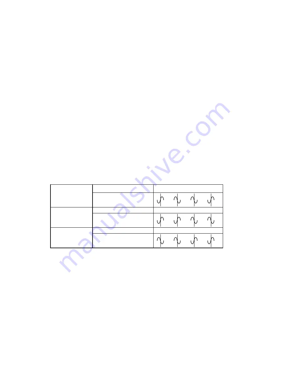
Table 3.3 provides an example. Here, we describe the difference between a 
NEAR and +1 color framing for NTSC outputs. Notice the vertical timing between 
the reference input and the analog output. In this example, there is a vertical delay 
of 1 field. If NEAR is selected, the output color framing (or burst locked sinewave) 
will follow the same subcarrier phase pattern, starting with field 1, as the reference 
input. That is, all analog output field 1 lines will have a positive going zero 
crossing of burst phase as all field 1 lines of the reference input, all output field 2 
lines will have a negative going zero crossing of burst phase as all field 2 lines of 
the reference input, and so on. 


On the other hand, if a color framing of +1 is selected, the subcarrier phase 
relationships of fields 3 and 4 of the reference input is transferred to fields 1 and 2 
of the analog output and the color framing continues as usual. That is, all analog 
output field 1 lines will have a negative going zero crossing of burst phase as all 
field 3 lines of the reference input, all output field 2 lines will have a positive going 
zero crossing of burst phase as all field 4 lines of the reference input, and so on. 


For NTSC analog outputs, only NEAR and +1 selections are available to adjust 
color framing. However, due to PAL’s 8 field color frame, the selections NEAR, 
+1, +2, and +3 are available. 


Table 3.3

   NTSC color framing example 


Reference input 

Field 

1 2 3 4 


Burst locked sinewave  


Analog output 

Field 

4 1 2 3 

(CFRM=NEAR) 

Burst locked sinewave 


Analog output 

Field 

4 1 2 3 

(CFRM=+1) 

Burst locked sinewave 


To select the desired setup level, perform the following steps: 


1.  Press SELECT to enter the menu. 

PROC

 is displayed. 

2.  Press the “+“ push-button until 

COMP

 is displayed. 

3. Press 

SELECT; 

SETP

 is displayed. Press the “+“ push-button until 

CFRM

 is 

displayed. 

4.  Press SELECT to enable the Color Framing Control menu. The current color 

framing selection


is displayed. 

5.  Use the “+” or “–“ push-button to choose the desired color framing selection. 

Press the “+ “ and “–“ push-buttons simultaneously to set the setup level to 

NEAR 

(default setting). 

6.  Press SELECT to store the new color framing selection. 

CFRM 

is displayed. 

7.  Press ESC to return to 

COMP

.  

8.  To return to normal mode, press ESC. 

Summary of Contents for DVP-101i

Page 1: ...tion M081 9900 201 Copyright 2002 MirandaTechnologies Inc Specifications may be subject to change Printed in Canada August 2002 DVP 101i imaging Series Miranda Technologies inc 3499 Douglas B Floreani St Laurent Québec Canada H4S 1Y6 Tel 514 333 1772 Fax 514 333 9828 www miranda com ...

Page 2: ...s essential and the customer so requests Miranda will at its option provide a service replacement or loaner part or product usually within 36 hours of factory notification weekends and holidays excluded All warranty exchange or loaner parts or products shall be shipped to the Buyer with a packing list clearly describing the items and stating the date of shipment Repaired parts or products will be ...

Page 3: ...nical Support Services at 514 333 1772 ELECTROMAGNETIC COMPATIBILITY This equipment has been tested for verification of compliance with FCC Part 15 Subpart B class A requirements for Digital Devices This equipment complies with the requirements of EN55022 Class A Electromagnetic Emissions En 60555 2 3 Disturbance in Supply Systems and EN50082 1 Electromagnetic Immunity How to contact us Head Offic...

Page 4: ...e Stauts Indicators 11 3 3 Menu Introduction 12 3 4 Digital ProcAmp Functions 15 3 4 1 Y Cb and Cr Gain Adjustments 15 3 4 2 Overall Gain Adjustment 15 3 4 3 Saturation Adjustment 15 3 4 4 Black Level Adjustment 16 3 4 5 Hue Adjustment 16 3 4 6 Cable Equalization 16 3 4 7 Horizontal Picture 17 3 5 Timing Adjustments 17 3 5 1 Frame Phasing 17 3 5 2 Vertical Timing Delay 18 3 5 3 Horizontal Timing D...

Page 5: ... 10 Configuration 26 3 10 1 Loading User Presets 26 3 10 2 Saving User Presets 27 3 11 Factory Reset 27 3 12 Direct Access Controls 27 3 12 1 Freeze Pushbutton 27 3 12 2 Test Pushbutton 27 4 Specifications 29 5 Schematic Diagrams 31 ...

Page 6: ...n and handling EDH is performed at the input and at the output Vertical and horizontal ancillary data are buffered through or blanked according to user selection Vertical interval data is buffered through blanked or processed on a line by line basis according to user selection An internal color bar generator further enhances the DVP 101i s functionality All outputs conform to the SMPTE 259M standa...

Page 7: ...ion Selectable HANC pass or blank Selectable VANC processing on a line by line basis pass blank process line 10 24 for format 525 and line 6 24 for format 625 Built in test pattern generator for color bars 75 100 white and black Parameters for 5 presets stored in non volatile memory Wide Narrow blanking for composite output as per SMTE 170M Control signal for future bypass relay on rear module Fra...

Page 8: ...essed by a DAP 712i module therefore two DAP modules may be used in conjunction with one DVP 101i one per audio group Figure 1 2 AES is extracted on DVP 101i processed on DAP 711i 712i and re inserted on DVP 101i Figure 1 3 Audio from the DAP 711i 712i is inserted on DVP 101i Figure 1 4 AES is extracted on DVP 101i and processed on DAP 711i 712i 4 2 2 AES DVP 101i DEMUX Frame Sync Proc Amp DAP 712...

Page 9: ...trates a typical hot switch setup For a smooth transfer to occur when switching between two sources set the FRZE MODE to ERR error on input signal Immediately after a switch is performed on the routing switcher DVP 101i will detect an input error thereby performing a freeze The DVP 101i automatically switches to the last errorless field or black Once the transfer between the two sources is complet...

Page 10: ...s For a closer look at card installation and removal refer to the housing frame s Guide to Installation and Operation 1 Remove the housing frame s front panel by rotating the thumb screws counter clockwise Pull on the handles 2 Select an empty slot 3 Carefully place the DVP 101i between a set of card guides and gently push the card towards the rear of the housing frame until the card s edge connec...

Page 11: ...nector is secured to its rear module A light pressure to mate the connectors may be required Pull lightly on the module verifying that it does not move 4 Replace the front panel door Note Up to two DAP 711i 712i module may be used in conjunction with the DVP 101i module when using the imaging Symphonie housing frame The DVP 101i must always be installed at the right of the DAP modules figure 2 2 b...

Page 12: ... move 3 Replace the housing frame s front panel 2 3 Rear Panel Label 2 3 1 imaging Quartet Quartet C Quartet M Solo Connector Label Connector labels have been shipped with your DVP 101i Select the label according to your housing frame model This label is to be installed on the housing frame s rear panel in order to identify the DVP 101i external connectors To install the label follow these steps 1...

Page 13: ...these steps while referring to Figure 2 2 1 On Symphonie s rear panel locate the appropriate connectors 2 Remove the rear label mounting screws from the rear module 3 Carefully apply the label to the connectors making sure the label s text is read from top to bottom 4 Replace the screws making sure not to damage the label Figure 2 5 Symphonie rear panel label installation ...

Page 14: ...sure to terminate this output with a 75 Ω terminator when it is not being used A valid analog composite reference signal will turn on the REF indicator located on the module s front end figure 3 1 The reference signal must be NTSC for 60 Hz sources and PAL for 50 Hz sources If there exists a line format mismatch between the reference input and the 4 2 2 input the REF indicator flashes 4 2 2 OUT 1 ...

Page 15: ... 5 DELAY 6 NC 7 NC 8 NC 9 NC 10 NC 1 NC Pin RJ 45 Connector Pin Location SMPTE 259M C 4 2 2 video input Studio reference or black input Reference loop through output Analog composite output NTSC PAL 4 2 2 loop through output DVP 101i 4 2 2 DIGITAL VIDEO PROCESSOR SYNCHRONIZER 1 2 1 2 Quartet Quartet C Solo Symphonie R C 4 2 2 loop through output Video processing delay GPI output IN 4 2 2 LOOP 4 2 ...

Page 16: ...rface 3 2 Line Format Error Detection and Reference Status Indicators The following indicators provide information on the DVP 101i s line format status Refer to Figure 3 1 for the correct indicator location 525 This LED turns on to indicate the FRS 101i has detected a 525 line format signal connected to 4 2 2 IN 625 This LED turns on to indicate the FRS 101i has detected a 625 line format signal c...

Page 17: ...he manual freeze is enabled It will also blink when the DVP 101i performs an automatic freeze caused by a loss of input or continuous input errors TEST This LED turns on when the internal test pattern is enabled AUDIO IN DETECTED Some of these LEDs will turn on to indicate the presence of audio groups on the input signal 3 3 Menu Introduction Most DVP 101i parameters are accessed and changed via a...

Page 18: ...tup value is stored for the current format ESC If ESC is pressed after making changes to a parameter the parameter is reset to the value it had prior to the change For example after changing the Cb value press ESC The menu returns to Cb and the previous Cb value is reloaded Automatic Exit From Menu After 1 Minute Interval If the menu is currently being accessed and no push button has been pressed ...

Page 19: ...NK HANC PASS BLNK S E E S E VANC PASS BLNK PROC USER E E S COMP SETP S E E S E CFRM 0 7 5 E E S HBLK NEAR 1 2 3 E E S CC NAR WIDE E E S IRE FRM FRZE MODE ERR LOSS OFF S E E S E TYPE FLD1 FLD2 FRM BLAK E E S CONF LOAD USR1 USR5 S E E S E SAVE USR1 USR5 E E S FACT NO YES S E E Note 1 If the user does not use a DAP 711i 712i the audio mux and demux selection should be set to OFF for proper operation ...

Page 20: ...the selected component 6 Press ESC to return to PROC 7 To return to normal mode press ESC 3 4 2 Overall Gain Adjustment The overall gain applies to the Y Cb and Cr gains simultaneously Note that relative gain setting differences are maintained between the individual components as an example if Y is set to 100 Cb to 50 and Cr to 0 an overall gain adjustment of 10 will result in Y 110 Cb 60 and Cr 1...

Page 21: ...button to set the required black level Press the and push buttons simultaneously to set the black level to default 5 Press SELECT to store the new black level 6 Press ESC to return to PROC 7 To return to normal mode press ESC 3 4 5 Hue Adjustment The hue adjustment ranges from 180 to 180 in steps of 0 5 the default being set at 0 Perform the following steps to adjust the hue 1 Press SELECT to ente...

Page 22: ...ess the and push buttons simultaneously to set the horizontal position to default 5 Press SELECT to store the new horizontal position 6 Press ESC to return to PROC 7 To return to normal mode press ESC 3 5 Timing Adjustments When the DVP 101i operates without a reference signal it operates in Frame Delay Frame Buffer mode the timing adjustment sets the processing delay between the input signal and ...

Page 23: ...ines format Follow these steps in order to adjust vertical timing delay 1 Press SELECT to enter the menu PROC is displayed 2 Depress the push button until TIMG is displayed 3 Press SELECT to enter the Timing menu FRAM is displayed Depress until VERT is displayed 4 Press SELECT to enable the vertical timing delay menu The current timing delay in video lines is displayed 5 Use the or push button to ...

Page 24: ...udio groups from the ancillary data space of the video input pass it to companion DAP 711i 712i Audio Processor modules and re embed it at the output see section 2 1 DVP 101i Mechanical Installation for details about DAP module installation Each audio group travels to the audio processor using its own bus called ABUS audio bus different parameters allow the audio functions to be configured for eac...

Page 25: ... push button to choose the desired audio group to insert Press the and push buttons simultaneously to set audio embedding to OFF 7 Press SELECT to store the new audio embedding setting MUX is displayed 8 Press ESC to return to ABUS 9 To return to normal mode press ESC Note When no DAP audio module is used the Audio Embedding function should be set to off for proper operation of the DVP 101i 3 6 3 ...

Page 26: ...able options for HANC blanking PASS All incoming HANC data is allowed to pass through to the output BLNK All incoming VANC data is blanked To change VANC blanking setting follow these steps 1 Press SELECT to enter the menu PROC is displayed 2 Press the push button until BLNK is displayed 3 Press SELECT HANC is displayed 4 Press SELECT to enable the HANC Blanking menu The current HANC Blanking sett...

Page 27: ...ed 2 Press the push button until BLNK is displayed 3 Press SELECT HANC is displayed Press the push button until VANC is displayed 4 Press SELECT to enable the VANC Blanking menu The current VANC Blanking setting is displayed 5 Use the or push button to choose the desired VANC Blanking setting Press the and push buttons simultaneously to set VANC Blanking to PASS default setting 6 Press SELECT to s...

Page 28: ...ze is disabled Note When a freeze condition occurs the horizontal and vertical blanking intervals HANC and VANC are blanked 3 8 2 Freeze Type The Freeze Type menu selects the type of image freeze to be executed if it is enabled by the Automatic Freeze Mode Refer to Table 3 2 for a description of each type of freeze To change the freeze type follow these steps 1 Press SELECT to enter the menu PROC ...

Page 29: ... the alarm To select the detection period or turn the feature off perform the following steps 1 Press SELECT to enter the menu PROC is displayed 2 Press the push button until INFZ is displayed 3 Press SELECT to enable the Input Freeze menu The current selection is displayed either OFF or a time interval in seconds 4 Use the or push button to choose the desired status Press the and push buttons sim...

Page 30: ...s all analog output field 1 lines will have a negative going zero crossing of burst phase as all field 3 lines of the reference input all output field 2 lines will have a positive going zero crossing of burst phase as all field 4 lines of the reference input and so on For NTSC analog outputs only NEAR and 1 selections are available to adjust color framing However due to PAL s 8 field color frame t...

Page 31: ...ween ON and OFF states perform the following steps 1 Press SELECT to enter the menu PROC is displayed 2 Press the push button until COMP is displayed 3 Press SELECT SETP is displayed Press the push button until CC is displayed 4 Press SELECT to enable the Closed Captioning menu The current status of set up on line 21 is displayed 5 Use the or push button to choose the desired line 21 set up status...

Page 32: ...hat this overwrites any existing configuration that was saved previously under that User Preset SAVE is displayed 7 Press ESC to return to CONF 3 11 Factory Reset It may be necessary at times to reset all parameters for 525 or 625 line inputs to their original values programmed during manufacturing Table 3 4 lists the default values To perform a factory reset follow these steps 1 Press SELECT to e...

Page 33: ...r bars with 100 white 100 color bars and black respectively When depressed the test pattern is enabled and the yellow LED located next to it lights up Depressing the Test pushbutton consecutively will cycle through the 3 test patterns depressing after BLAK is displayed disables the test pattern output ...

Page 34: ...UT Ext Ref SMPTE 170M ITU 624 4 or 2 Vp p 4 Vp p Composite Sync Return Loss 35 dB up to 5 75 MHz DIGITAL OUTPUT Signal 2 4 2 2 SMPTE 259M C 270 Mbps Return Loss 15 dB up to 270 MHz Jitter Wideband 0 2 UI 0 74ns p p Delay Tracking Miranda video audio tracking signal Audio Bus I O 10 pin connector to audio processor COMPOSITE ANALOG OUTPUT Signal 2 NTSC 525 60 SMPTE 170M PAL 625 50 ITU 624 4 PROCESS...

Page 35: ...RMANCE ANALOG OUTPUT Quantization 10 bits Sampling 54 MHz 4X Oversampling Freq Response 0 1 dB to 5 5 MHz Noise Unweighted 62 dB to 5 75 MHz Diff Gain 1 Diff Phase 1 degree MISCELLANEOUS Audio Embedding SMPTE 272M ABD Test Signal 75 color bars with 100 white 100 color bars black Power 9 W ...

Page 36: ...31 5 Schematic DIagrams ...

Reviews: